 |
|||
|
|
|||
|
|
|||
| ||||||||||
|
|
 TM 10-3930-660-24-2
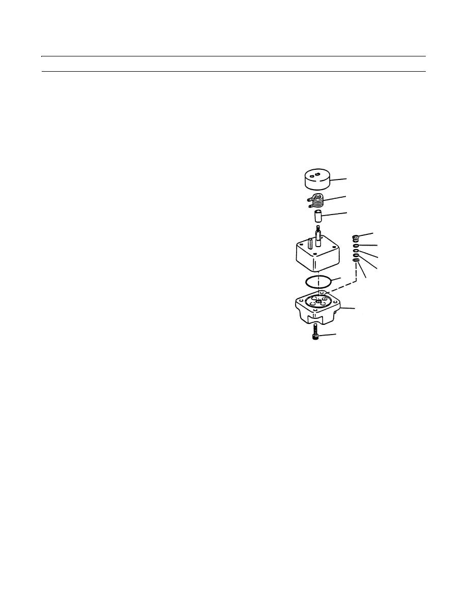
FRAME TILT VALVE REPAIR - CONTINUED
0259 00
ASSEMBLY
NOTE
Wipe all sealing surfaces of valve clean and dry. Apply film of clean hydraulic oil to all seals as they are
installed.
1.
If removal was necessary, install stop pin (19) in cap (20).
2.
Install back-up ring (18) and new O-ring (17) in bore of cap (20).
3.
Slide shaft (13) through hole in cap (20). Install bush-
1
ing (3) on shaft (13).
4.
Use pliers to install spring (2) on shaft (13).
2
5.
Install hub (1).
3
6.
Install bearing race (14) and bearing (15).
7.
Install stop plate (16). Ensure that stop pin (19) is cen-
7
tered in wide gap of plate (16).
9
8.
Install disk assembly (12) on shaft (13). The side of
disk assembly (12) with holes drilled through it must
8
face away from cap (20). Ensure that one of two holes
9
drilled on outer surface of disk assembly (12) align
6
10
with stop pin (19).
5
4
409-1387
9.
Install shaft washer (11) on shaft (13).
10.
Install four seal springs (10), eight back-up rings (9), four new O-rings (8) and four seals (7) in body (4).
11.
Install new O-ring (6) in groove on body (5).
12.
Install body (5) to cap (20). Install four socket head screws (4).
13.
Install frame tilt valve (WP 0180 00).
14.
Operate vehicle, check for proper operation and leaks (TM 10-3930-660-10).
END OF WORK PACKAGE
0259 00-3/(-4 Blank)
|
|
Privacy Statement - Press Release - Copyright Information. - Contact Us |
