 |
|||
|
|
|||
|
|
|||
| ||||||||||
|
|
 TM 10-3930-660-24-2
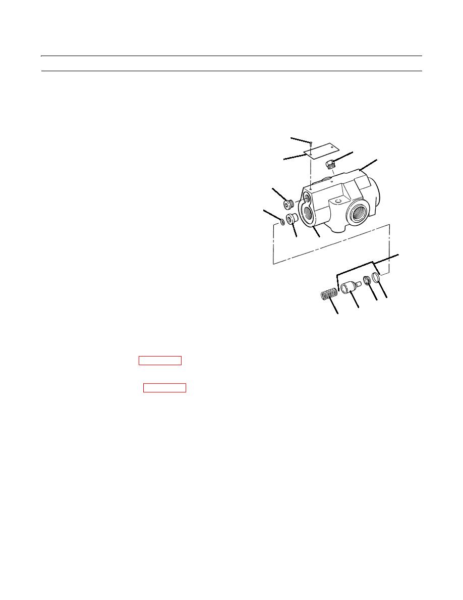
FRAME TILT/BRAKES RELIEF VALVE REPAIR - CONTINUED
0258 00
DISASSEMBLY - CONTINUED
7.
Remove spring (13), poppet assembly (14) and O-ring
(15) from valve seat (19). Discard O-ring.
8.
Remove retainer (16), screw (17) and poppet (18), if
necessary.
23
NOTE
20
Do not remove seat from body.
24
9.
Remove plugs (21 and 22) from valve body (20), if
necessary.
21
10.
Remove two screws (23) and nameplate (24) from
valve body (20), if necessary.
15
20
19
14
17 16
18
13
409-4104
CLEANING
See Cleaning instructions (WP 0316 00).
INSPECTION
See Inspection instructions (WP 0317 00).
ASSEMBLY
NOTE
Wipe all sealing surfaces of valve clean and dry. Apply film of clean hydraulic oil to all seals as they are
installed.
1.
If removal was necessary, install nameplate (24) and two screws (23) on valve body (20).
2.
If removal was necessary, install plugs (21 and 22) on valve body (20).
0258 00-2
|
|
Privacy Statement - Press Release - Copyright Information. - Contact Us |
