 |
|||
|
|
|||
|
|
|||
| ||||||||||
|
|
 TM 10-3930-660-24-2
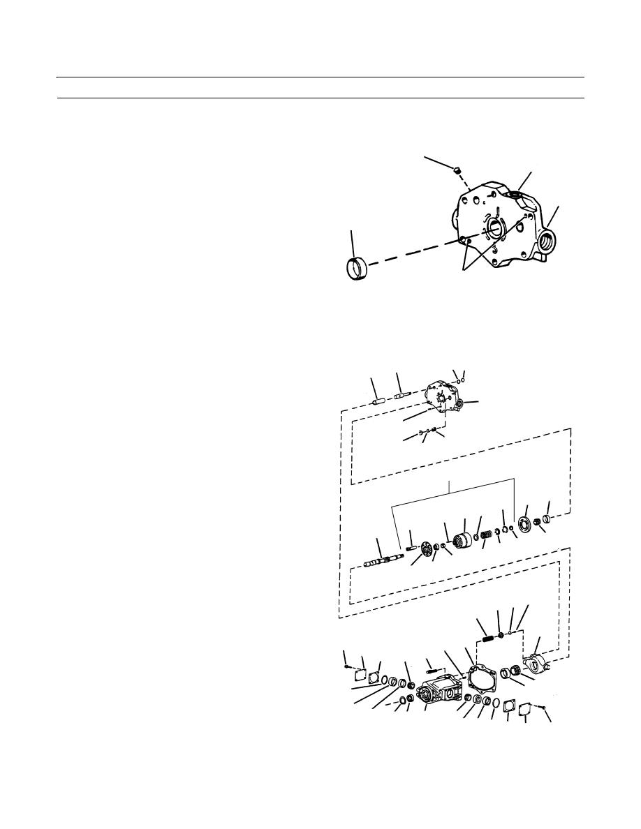
PISTON PUMP MAINTENANCE - CONTINUED
0256 00
ASSEMBLY - CONTINUED
24. Install correct shims (27).
25.
Install pintle cover (29) and cross torque cover screws
45
A
(28) to 175-185 lb-in. (20-21 Nm).
NOTE
3
Yoke rotation will be stiff, but should be
48
loose enough to be moved by hand
(approximately 20 lb-in. (2.25 Nm)
torque). This tightness/drag indicates that
bearings are preloaded. If yoke cannot be
moved by hand, preload is too great and
B
the preload adjustment must be repeated
409-1485
until correct.
26.
Use fabricated tool and an arbor press to install new bearing race (48). Press race (48) until it bottoms against shoulder
in valve block (3).
NOTE
47 46
8
7
Check flatness of valve block face in area
around locating pin holes (B) and at
3
mounting screw (A) holes. If necessary,
use an India stone to remove burrs or
12
raised metal in these areas.
44
42
43
27.
Install pipe plug (45) into valve block.
18
NOTE
48
11
21
17 23
16
If the shaft bearings, shaft, valve block or
23
15
housing were not replaced, use the bearing
13
spacer removed during disassembly to pre-
14
20 22
load the shaft and perform step 28. If any of
25
these items were replaced, preload adjust-
24
19
ment is required.
34 36 37
The bearing spacer kit contains several dif-
35
ferent sizes of bearing spacers.
26
49 10
28.
Install thickest bearing spacer (14) over driveshaft
28 29
9
(15) with chamfer facing into housing (6).
27
31
29.
Slide bearing (13) onto shaft (15). Small diameter of
38
bearing must face out of housing.
39
32
33
30.
Temporarily install bearing (6) on valve block (3). Do
409-1473
30
31
40 41 6
not install gasket (10) or rotating group parts (18) at
30 33 32 27 29
28
six screws (9) to 5 lb-in. (0.5 Nm).
0256 00-9
|
|
Privacy Statement - Press Release - Copyright Information. - Contact Us |
