 |
|||
|
|
|||
|
|
|||
| ||||||||||
|
|
 TM 10-3930-660-24-2
FRONT DIFFERENTIAL CARRIER ASSEMBLY REPLACEMENT - CONTINUED
0243 00
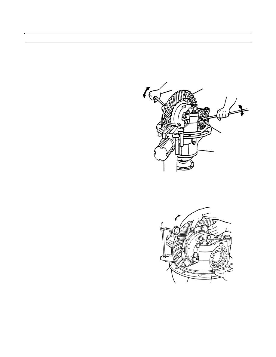
ADJUSTMENT - CONTINUED
4.
Loosen the bearing adjustment ring (15) opposite ring gear (22) so that a small amount of end play shows on dial indica-
tor. Move differential assembly and ring gear left and right with pry bars while reading dial indicator. Do not allow pry
bars to touch bearings (18 thru 20).
5.
Tighten bearing adjustment ring (15) opposite ring
gear (22) so that no end play shows on dial indicator.
Move the differential assembly and ring gear left and
22
right as needed.
6.
Tighten each bearing adjusting ring (15) one notch
from zero end play measured in step 5.
7.
Check runout of ring gear (22).
8.
Attach dial indicator on mounting flange of differen-
tial carrier (2). Adjust dial indicator so that plunger is
against back surface of ring gear (22).
15
9.
Adjust dial of indicator to zero.
2
409-1254
10.
Rotate differential assembly and ring gear (22) and read dial indicator. If runout of ring gear exceeds 0.008 in. (0.203
mm), remove differential assembly and ring gear and inspect differential assembly for problem. Replace defective parts
and reinstall differential assembly and ring gear into differential carrier (2). Repeat preload adjustment of differential
11.
Adjust backlash of ring gear (22).
12.
Attach a dial indicator to the mounting flange on dif-
ferential carrier (2).
13.
Adjust dial indicator so that plunger is against the
tooth surface on ring gear (22).
14.
Adjust dial of indicator to zero.
15.
Hold bevel pinion in position.
16.
Read dial indicator while rotating ring gear (22) a
small amount in both directions.
22
17.
Adjust backlash of old gear set to setting measured
before carrier was disassembled (0.008 to 0.018 in.),
15
2
(0.203 to 0.457 mm).
409-1255
18.
If new gear set is installed, adjust backlash to 0.012 in. (0.305 mm).
0243 00-4
|
|
Privacy Statement - Press Release - Copyright Information. - Contact Us |
