 |
|||
|
|
|||
|
|
|||
| ||||||||||
|
|
 TM 10-3930-660-24-1
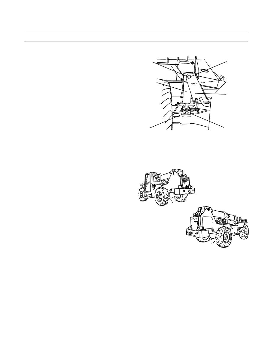
FRAME TILT CYLINDER REPLACEMENT - CONTINUED
0183 00
INSTALLATION - CONTINUED
5.
Connect two hydraulic hoses (5) to frame tilt cylinder
2
3
(4) as tagged.
6.
Align and connect base pivot pin (3).
7.
Start engine, check for proper operation and leaks
5
4
(TM 10-3930-660-10).
8.
Extend frame tilt cylinder (4) to align rod end hole and
6
upper bracket hole.
9.
Stop engine (TM 10-3930-660-10).
409-4074
8
7
NOTE
Apply anti-seize compound to base pivot pin as installed.
10.
Install base pivot pin (3).
11.
Install retaining ring (2).
12.
Remove blocking from between both rear frame tilt
stop pads (1) and rear axle housing.
1
409-689
1
409-690
13.
Start engine (TM 10-3930-660-10).
14.
Purge air from frame tilt cylinder hydraulic circuit by operating frame tilt function five times.
15.
Stop engine and relieve hydraulic pressure by operating frame tilt controls (TM 10-3930-660-10).
END OF WORK PACKAGE
0183 00-4
|
|
Privacy Statement - Press Release - Copyright Information. - Contact Us |
