 |
|||
|
|
|||
|
|
|||
| ||||||||||
|
|
 TM 10-3930-660-24-1
FRAME TILT CYLINDER REPLACEMENT - CONTINUED
0183 00
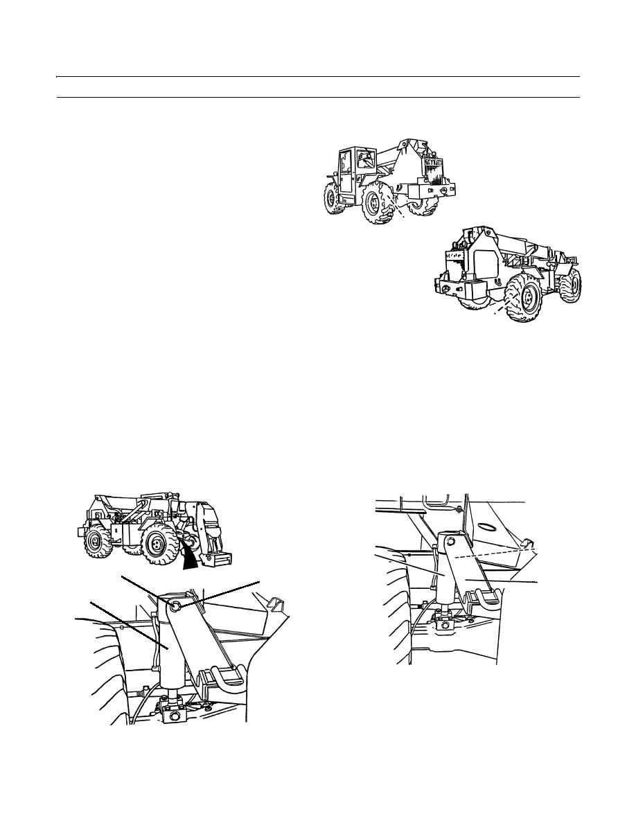
REMOVAL
1.
Use frame tilt function to level the vehicle (TM 10-
3930-660-10).
NOTE
Frame tilt stop pads are located on each
side of the rear axle.
1
409-689
2.
Insert blocking between both rear frame tilt stop pads
(1) and rear axle housing.
3.
Remove retaining ring (2) from base pivot pin (3).
1
409-690
4.
With assistance, support frame tilt cylinder (4) and remove base pivot pin (3).
5.
Start engine and retract frame tilt cylinder (4) by moving frame control to the right (TM 10-3930-660-10).
6.
Stop the engine (TM 10-3930-660-10).
NOTE
If more than one hydraulic line is to be removed, identify lines to assure proper installation. Use container to
catch any hydraulic oil that may drain from system.
7.
Disconnect two hydraulic lines (5) located between frame tilt cylinder (4) and cylinder support bracket (6).
5
4
3
2
6
4
409-4073
409-4072
0183 00-2
|
|
Privacy Statement - Press Release - Copyright Information. - Contact Us |
