 |
|||
|
|
|||
|
Page Title:
BOOM CYLINDER FLOW CONTROL VALVE REPLACEMENT |
|
||
| ||||||||||
|
|
 TM 10-3930-660-24-1
BOOM CYLINDER FLOW CONTROL VALVE REPLACEMENT
THIS WORK PACKAGE COVERS
Removal, Installation
INITIAL SETUP
Tools and Special Tools
Equipment Condition
Vehicle parked on level ground (TM 10-3930-660-
Tool kit, general mechanic's (Item 39, WP 0324 00)
10)
Shop equipment, common no. 1 (Item 20, WP 0324
Boom fully lowered and MLRS attachment resting
on ground (TM 10-3930-660-10)
Transmission cover removed (WP 0150 00)
Materials/Parts
Cap and plug set (Item 8, WP 0323 00)
Tag, marker (Item 57, WP 0323 00)
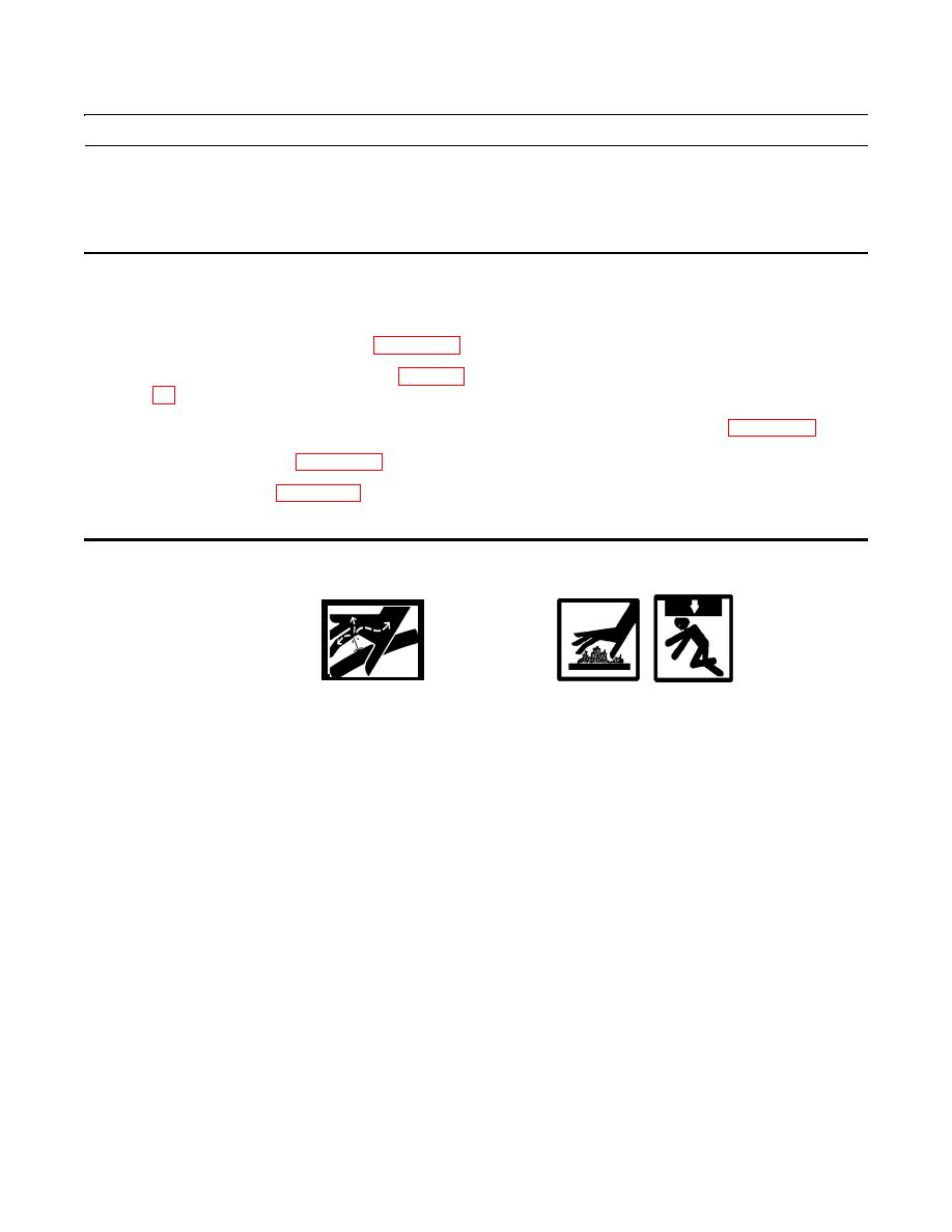
WARNING
Do NOT remove hydraulic tank filler cap or disconnect or remove any hydraulic system line or fitting
unless hydraulic system pressure has been relieved. Hydraulic system pressure can be over 3,000 psi
(20684 kPa), even with engine and pump OFF. To relieve pressure, lower all hydraulic attachments to
the ground and shut down engine. Move control levers through all operating positions, then SLOWLY
loosen hydraulic tank filler cap. After maintenance, tighten all connections before applying pressure.
Escaping hydraulic fluid under pressure can penetrate the skin, causing injury or death.
At operating temperature hydraulic oil is hot. Allow hydraulic oil to cool before disconnecting any
hydraulics. Failure to do so could result in injury.
When working underneath the boom, always support the boom using blocks, jackstands or other rigid
and stable supports. Combined weight of boom and MLRS attachment is approximately 6,300 lb (2858
kg). Failure to adequately support the boom could result in severe injury or death.
CAUTION
Wipe are clean around all hydraulic connections to be opened during removal and disassembly. Cap oil lines
and plug holes after removing lines. Contamination of the hydraulic system could result in premature failure.
NOTE
If more than one hydraulic line is to be removed, identify lines to ensure proper installation. Use container to
catch any hydraulic oil that may drain from system.
|
|
Privacy Statement - Press Release - Copyright Information. - Contact Us |
