 |
|||
|
|
|||
|
|
|||
| ||||||||||
|
|
 TM 10-3930-660-24-1
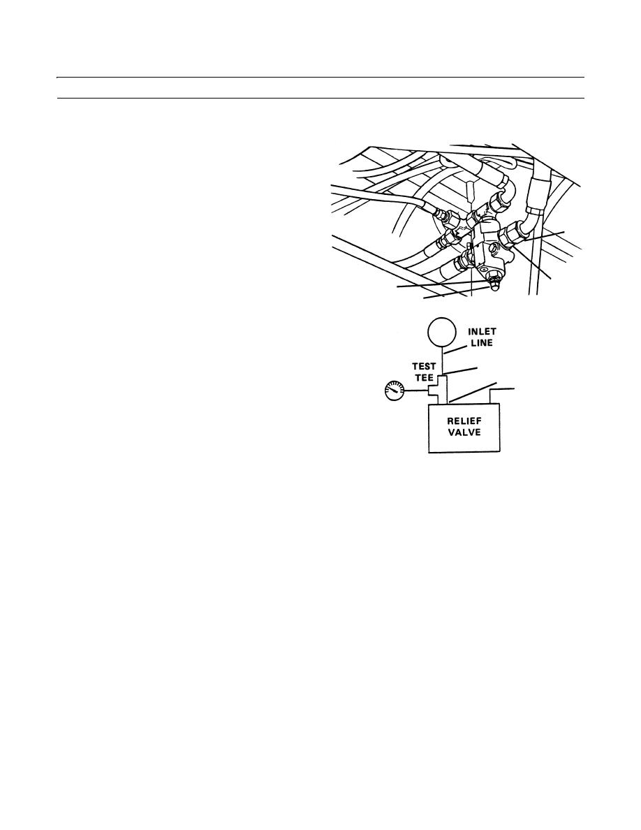
RELIEF VALVE, FRAME TILT/BRAKES REPLACEMENT - CONTINUED
0178 00
TESTING AND ADJUSTMENT
1.
Remove relief valve inlet line (7).
2.
Connect a test tee to inlet line (7).
3.
Connect other side of test tee to relief valve inlet port
(8).
4.
Connect 0 to 5000 psi (34474 kpa) pressure gauge to
7
test tee.
5.
Start engine (TM 10-3930-660-10).
8
10
NOTE
9
409-672
Engine may be operated at idle or full throttle
when performing pressure tests.
6.
Read relief valve pressure on gauge. Pressure range is
7
1,700-1,800 psi (11721-12410 kPa). If relief valve
8
pressure is not within specifications, adjust as follows:
a.
Remove acorn nut (9) covering slotted head adjust-
ing screw.
b.
While holding adjusting screw, loosen and back off
jamnut (10) which secures adjusting screw.
409-673
c.
To increase relief pressure, turn adjusting screw
clockwise (in). To decrease pressure, turn adjusting
screw counterclockwise (out).
d.
When desired relief pressure is obtained, hold
adjusting screw in position and tighten jamnut (10).
Install acorn nut (9).
7.
Stop engine (TM 10-3930-660-10).
8.
Remove pressure gauge (TM 10-3930-660-10).
9.
Remove pressure gauge from test tee.
10.
Remove test tee.
11.
Remove test tee from relief valve.
12.
Remove inlet hydraulic hose from test tee.
13.
Connect inlet hydraulic hose to relief valve.
14.
Connect inlet hydraulic hose (7) to relief valve. Tighten securely.
END OF WORK PACKAGE
0178 00-3
|
|
Privacy Statement - Press Release - Copyright Information. - Contact Us |
