 |
|||
|
|
|||
|
Page Title:
ADJUSTMENT OF BOOM LOWER RELIEF VALVE |
|
||
| ||||||||||
|
|
 TM 10-3930-660-24-1
MAIN CONTROL VALVE MAINTENANCE - CONTINUED
0175 00
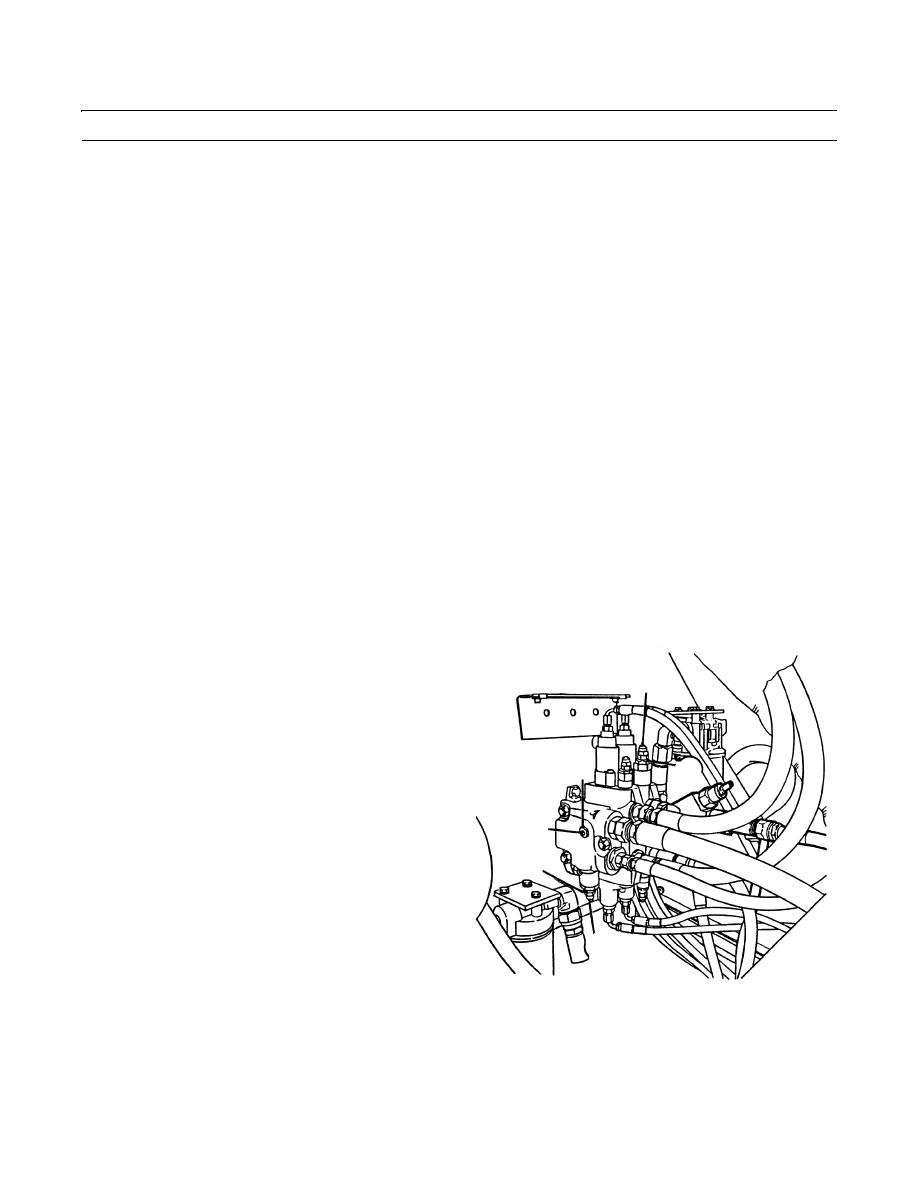
ADJUSTMENT OF BOOM LOWER RELIEF VALVE
NOTE
The main relief valve pressure must be adjusted above normal operating pressure to permit the boom lower
relief valve pressure to be adjusted. Main relief valve pressure is then returned to normal operating pressure
at the end of this procedure.
1.
Remove main relief valve plug assembly (11).
2.
Connect 0 to 5,000 psi (0 to 34474 kPa) pressure gauge to plug port (12).
3.
Remove acorn nut (13) covering slotted head adjusting screw (14).
4.
While holding adjusting screw (14), loosen and back off jamnut (15) which secures adjusting screw.
NOTE
Engine may be operated at idle or full throttle when performing pressure tests.
5.
Start engine (TM 10-3930-660-10).
6.
Operate boom extend, retract, hoist or lower function until hydraulic oil is passing over relief valve. Continue to hold
hydraulic lever in that position so oil passes over relief valve during relief valve adjustment.
7.
Turn adjusting screw (14) clockwise (in) until pressure on gauge reads 3,100 psi (21374 kPa).
8.
Release hydraulic function lever.
9.
Remove acorn nut (22) covering slotted head adjust-
ing screw (23).
22,23
10.
While holding adjusting screw (23), loosen and back
off jamnut (24) which secures adjusting screw.
11.
Operate boom lower function until boom is fully low-
ered. Continue to hold boom control lever in position
12
24
so hydraulic oil passes over relief valve.
12.
Read relief valve pressure on pressure gauge.
13.
Adjust boom lowering relief valve pressure between
11
1,000 to 1,100 psi (6895 to 7584 kPa), when desired
relief pressure is obtained, release boom hoist lever
15
(TM 10-3930-660-10).
14.
To increase relief pressure, turn adjusting screw (23)
clockwise (in). To decrease pressure, turn adjusting
screw counterclockwise (out).
13,14
15.
Hold adjusting screw (23) in position and tighten jam-
nut (24). Install acorn nut (22).
409-661
Perform steps 4 through 13 of Adjustment of Main
16.
Relief Valve.
END OF WORK PACKAGE
0175 00-8
|
|
Privacy Statement - Press Release - Copyright Information. - Contact Us |
