 |
|||
|
|
|||
|
|
|||
| ||||||||||
|
|
 TM 10-3930-660-24-1
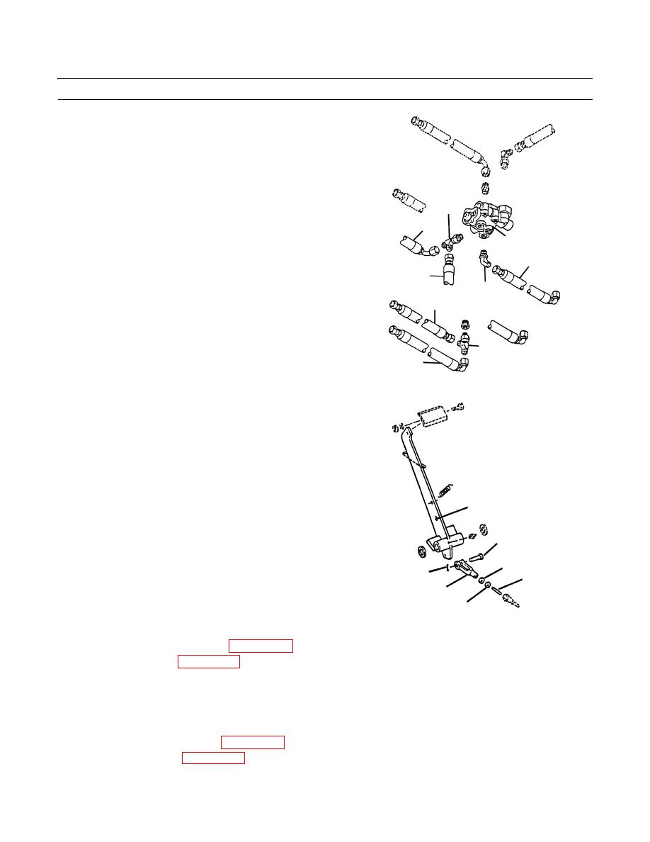
BRAKE CONTROL VALVE MAINTENANCE - CONTINUED
0131 00
INSTALLATION - CONTINUED
12.
Connect hose (12 and 13) to tee (14) at valve (6) as
tagged.
13.
Connect hose (9 and 10) to tee (11) at valve (6) as
tagged.
14.
Connect hose (7) to elbow (8) at valve (6) as tagged.
14
15.
Rotate pushrod pin (3) and/or clevis (4) in or out as
13
required until clevis pin (2) fits freely through holes
6
on clevis (4) and brake pedal arm (5).
7
16.
Secure clevis (4) to brake pedal arm (5) with clevis pin
(2) and new cotter pin (1).
12
8
10
11
9
409-511
17.
Tighten jamnuts (20 and 21) on pushrod pin (3).
5
2
20
1
3
4
21
409-512
18.
Connect hydraulic pressure switch (WP 0077 00).
19.
Fill the hydraulic tank (WP 0032 00).
CAUTION
The brake system and hydraulic accumulator must be bled as soon as the brake control valve is installed. If
this is not done, air in the system may not allow the brakes to release and may cause severe brake system
damage.
20.
Bleed the hydraulic accumulator (WP 0132 00).
21.
Bleed the brake system (WP 0129 00).
0131 00-5
|
|
Privacy Statement - Press Release - Copyright Information. - Contact Us |
