 |
|||
|
|
|||
|
|
|||
| ||||||||||
|
|
 TM 10-3930-660-24-1
ENGINE OIL PRESSURE SENDER MAINTENANCE - CONTINUED
0099 00
INSTALLATION - CONTINUED
NOTE
Perform steps 4 through 6 for the 152 hp engine.
4.
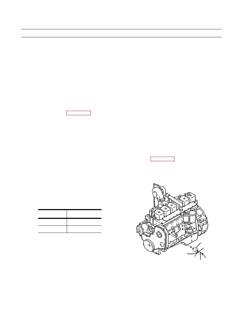
Apply loctite to threads of fitting (5) and install fitting into engine (6).
5.
Apply loctite to threads of sender (4).
6.
Install sender (4) into fitting (5).
NOTE
Perform step 7 for both engines.
7.
Connect electrical lead (3) with new lockwasher (2) and nut (1).
8.
Connect battery cables (WP 0107 00).
TESTING
1.
Remove nut (1) and lockwasher (2) to disconnect electrical lead (3) at sender (4). Discard lockwasher.
NOTE
Do not remove sender from engine.
2.
Connect one ohmmeter lead to the sender terminal (A) and the other lead to the engine ground.
3.
Use STE/ICE-R to monitor engine oil pressure. See STE/ICE-R procedures (WP 0008 00).
4.
Start the engine and observe both the STE/ICE-R oil pressure readout and the ohmmeter. The pressure sender (4) should
have the following resistance readings.
NOTE
The 0 psi reading should be done at a
decreasing pressure. The 40 psi reading
should be read on an increasing pressure.
Oil Pressure
Resistance
0 psi
227-257 ohms
40 psi
92-114 ohms
5.
Replace sender (4) if resistance requirements are not
4
met. See Installation.
3
6.
Connect electrical lead (3) at sender (4). Install new
lockwasher (2) and nut (1).
A
1
2
409-367
END OF WORK PACKAGE
0099 00-3
|
|
Privacy Statement - Press Release - Copyright Information. - Contact Us |
