 |
|||
|
|
|||
|
Page Title:
BRAKE HYDRAULIC PRESSURE SWITCH MAINTENANCE |
|
||
| ||||||||||
|
|
 TM 10-3930-660-24-1
BRAKE HYDRAULIC PRESSURE SWITCH MAINTENANCE
THIS WORK PACKAGE COVERS
Removal, Installation, Testing
INITIAL SETUP
Materials/Parts - Continued
Tools and Special Tools
Tool kit, general mechanic's (Item 39, WP 0324 00)
Varnish, anti-fungus (Item 59, WP 0323 00)
Shop equipment, common no. 1 (Item 20, WP 0324
Equipment Condition
Vehicle parked on level ground (TM 10-3930-660-
Materials/Parts
10)
Sealant, Loctite (Item 48, WP 0323 00)
Battery cables disconnected (WP 0107 00)
Tag, marker (Item 57, WP 0323 00)
REMOVAL
NOTE
Tag all electrical connections before removing for use during installation.
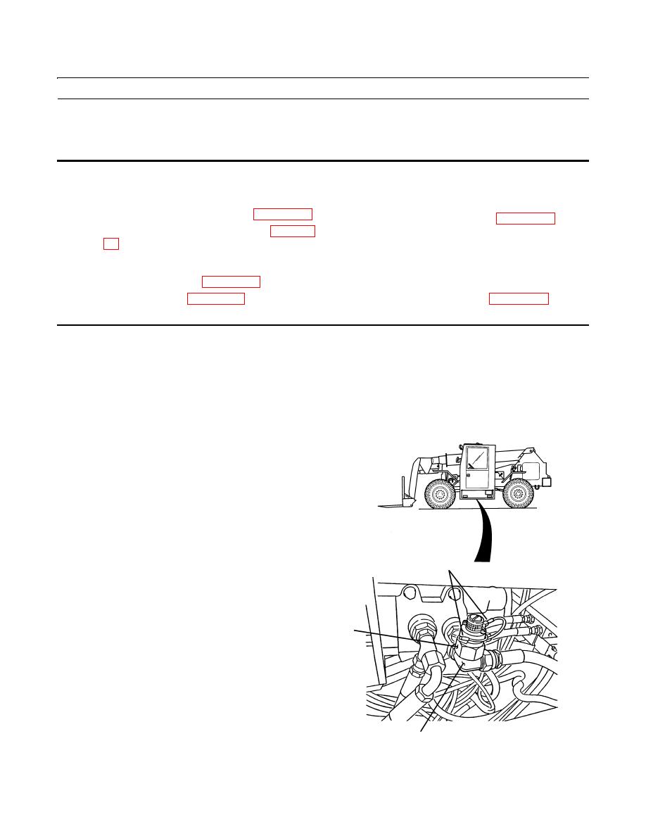
The brake hydraulic pressure switch is located under the vehicle cab, mounted on an elbow attached to the
brake control valve.
1.
With the engine off, pump the brake pedal a minimum
of 20 times to exhaust stored pressure in the brake sys-
tem.
2.
Disconnect two female connectors (1) of vehicle wir-
ing harness from two male connectors (2) at brake
hydraulic pressure switch (3).
3.
Place a container to catch hydraulic oil that will
briefly spill out of elbow (4) after switch (3) is
removed.
1,2
3
4
409-4027
|
|
Privacy Statement - Press Release - Copyright Information. - Contact Us |
