 |
|||
|
|
|||
|
|
|||
| ||||||||||
|
|
 TM 10-3930-660-24-1
FUEL SUPPLY LINES REPLACEMENT (152 HP) - CONTINUED
0038 00
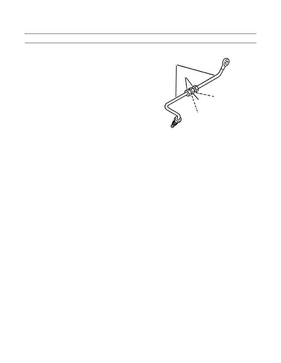
REMOVAL - CONTINUED
9.
If necessary, loosen nuts (18) and remove halves of
11
line (11) from union (19).
10.
If necessary, remove and discard seals (20) from
18
halves of line (11).
20
19
20
409-192
INSTALLATION
1.
If removed, install two new seals (20) to halves of line (11).
2.
If removed, position halves of line (11) on union (19) and tighten two nuts (18).
3.
Position line (11) on injection pump (17) and tighten nut (16) to secure.
4.
Place to new sealing washers (15) at end of line (11).
5.
Install fluid passage bolt (14) and adapter (13) as an assembly.
6.
Install hose (12) to adapter (13).
7.
Place two new sealing washers (10) at end of line (1). Position line (1) on engine and pump (3).
8.
Install adapter (7), tee (8), and fluid passage bolt (9) as an assembly.
NOTE
Apply loctite to sender.
9.
Install sender (5) to tee (8).
10.
Connect hose (6) to adapter (7).
11.
Connect female plug of vehicle wiring harness (4) to male plug of fuel pressure sender (5) as tagged.
12.
Tighten nut (2) on line (1) at pump (3).
13.
Start engine and check for leaks (TM 10-3930-660-10).
END OF WORK PACKAGE
0038 00-3
|
|
Privacy Statement - Press Release - Copyright Information. - Contact Us |
