| |
TM10-3930-660-20
18-32.
BOOM HOIST CYLINDERS - REPLACE (Cont'd)
Apply anti-seize compound to lower pivot
pin (7) as installed.
2.
ALIGN CYLINDER BASE LOWER MOUNTING
HOLES AND INSTALL LOWER PIVOT PIN
(7), SCREW (9) AND NEW LOCKNUT (8).
3.
CONNECT HYDRAULIC LINES (5 AND 6) AS
TAGGED DURING CYLINDER (2) REMOVAL.
4.
CAREFULLY RAISE CYLINDER
LIFTING DEVICE UNTIL ROD
CYLINDER (2) IS AIMED AT
MOUNTING HOLE ON BOOM.
(2) USING
EYE OF
PIVOT PIN
Have assistant signal operator
eye of cylinder (2) is aligned
pivot pin hole.
when rod
with boom
If installing both cylinders (2) at the
same time, note that in step 5 one
cylinder will extend, and the other will
remain stationary.
Cylinder (2) that extended must be
aligned and then secured to boom with
pivot pin (1).
When cylinder (2) that extended is
secured to boom, other cylinder (2) will
respond to controls, and can be extended
as
5.
6.
7.
well.
START ENGINE AND RUN AT FULL
THROTTLE, TM10-3930-660-10.
EXTEND CYLINDER ROD UNTIL UPPER PIVOT
PIN (1) CAN BE INSTALLED.
REPOSITION
CYLINDER (2), AS NECESSARY, USING
LIFTING DEVICE.
STOP ENGINE, TM10-3930-660-10.
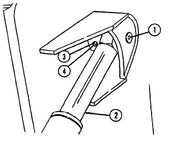
Apply anti-seize compound to upper pivot
pin (1) as installed.
18-130
8.
9.
10.
11.
INSTALL UPPER PIVOT PIN (1), SCREW (4)
AND NEW LOCKNUT (3).
DISCONNECT LIFTING DEVICE FROM
CYLINDER (2) AND BOOM. REMOVE
BOARD FROM ACROSS VEHICLE DECK.
BLEED AIR FROM HYDRAULIC SYSTEM.
a.
b.
c.
Start engine, TM10-3930-660-10.
Operate boom hoist functions.
Raise and lower boom five times.
Stop engine and relieve hydraulic
pressure by operating boom hoist
functions of hydraulic joystick,
TM10-3930-660-10.
INSTALL TRANSMISSION COVER,
PARA. 16-6.
|