| |
TM10-3930-660-20
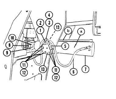
18-16.
MLRS ATTACHMENT CYLINDER - REPLACE (Cont‘d)
2. INSTALL TWO BEARING
ATTACHMENT CYLINDER
CAPS (5) AND MLRS
(7).
Install bearing caps (5) so that jack
bolt holes (13) are positioned as-shown.
Position cylinder (7) with the rod end
oil feed tube (b) up.
a. Apply Loctite 242 to six bolts
(11) .
b. Install six bolts (11) and six new
lockwashers (12).
c. Repeat steps a-b for other
bearing cap (5).
3. SUPPORT REAR PORTION OF MLRS
ATTACHMENT CYLINDER (7) USING A HOIST
AND SLING OR OTHER SUITABLE LIFTING
DEVICE.
Failure to support rear portion (a) of
MLRS attachment cylinder (7) when
installing pivot pin (8) may cause
personal injury and damage to cylinder
(7).
Apply anti-seize compound to pivot pin
(8).
4. INSTALL PIVOT PIN (8).
a. Secure pivot pin (8) with bolt (10)
and new locknut (9).
b. Raise or lower MLRS attachment
cylinder (7) as needed to ease
pivot pin (8) installation.
5. INSTALL TWO HYDRAULIC LINES (6). USE
TAGS TO IDENTIFY CONNECTIONS.
6. INSTALL NEW LOCKWASHER (4), CLAMP (3),
NEW LOCKWASHER (2) AND CAPSCREW (1) TO
EACH OF THE TWO BEARING CAPS (5).
Position hydraulic lines (6) in clamps
(3) so cylinder (6) can fully extend.
7. CYCLE MLRS ATTACHMENT CYLINDER (7)
FIVE TIMES TO BLEED ANY AIR IN
HYDRAULIC SYSTEM, TM10-3930-660-10.
Excessive air in hydraulic system may
temporarily prevent cylinder (7) from
operating. Attempt to cycle cylinder
(7) as required until its operation is
smooth and it fully extends and
retracts.
18-66
|