| |
TM10-3930-660-20
18-6.
MAIN CONTROL VALVE ASSEMBLY - ADJUST/REPLACE (Cont’d)
ADJUSTMENT - BOOM LOWER RELIEF VALVE
The main relief valve pressure must be
adjusted above normal operating pressure
to permit the boom lower relief valve
pressure to be adjusted.
Main relief valve pressure is then
returned to normal operating pressure at
the end of this procedure.
1. CONNECT PRESSURE GAUGE TO VALVE PORT.
a.
b.
c*
d.
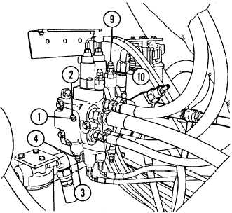
Remove main relief valve plug
assembly (1).
Connect O to 5000 psi pressure
gauge to plug assembly port (2).
Remove acorn nut (3) covering
slotted head adjusting screw.
While holding adjusting screw,
loosen and back off jam nut (4)
which secures adjusting screw.
3. ADJUST BOOM LOWERING RELIEF VALVE
2. ADJUST MAIN RELIEF VALVE PRESSURE TO
3,100 psi.
Engine may be operated at idle or full
throttle when performing pressure tests.
a.
b.
c.
d.
Start engine, TM10-3930-660-10.
Operate boom extend, retract,
hoist or lower function until
hydraulic oil is passing over
relief valve.
Continue to hold
hydraulic lever in that position
so oil passes over relief valve
during relief valve adjustment.
Turn adjusting screw clockwise
(in) until pressure on gauge reads
3,100 psi.
Release hydraulic function lever.
PRESSURE BETWEEN 1000 AND 1100 psi.
a.
b.
c.
d.
e.
Remove acorn nut (9) covering
slotted head adjusting screw.
While holding adjusting screw,
loosen and back off jam nut (10)
which secures adjusting screw.
Operate boom lower function
until boom is fully lowered.
Continue to hold boom control
lever in position so hydraulic oil
passes over relief valve.
Read relief valve pressure on
pressure gauge.
To increase relief pressure, turn
adjusting screw clockwise (in).
To decrease pressure, turn
adjusting screw counterclockwise
(out) .
18-27
|