| |
TM10-3930-660-20
18-6.
MAIN CONTROL VALVE ASSEMBLY - ADJUST/REPLACE (Cont’ d)
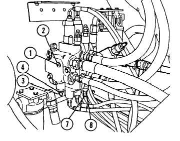
7. INSTALL MAIN RELIEF VALVE PLUG
ASSEMBLY.
Screw main relief valve plug
assembly (1) into port (2) and
tighten.
8. REPLACE TRANSMISSION COVER,
PARA. 16-6.
ADJUSTMENT - BOOM HOIST RELIEF VALVE
1. CONNECT PRESSURE GAUGE TO VALVE PORT.
The main relief valve pressure must be
adjusted above normal operating pressure
to permit the boom hoist relief valve
pressure to be adjusted.
Main relief valve pressure is then
returned to normal operating pressure at
the end of this procedure.
a. Remove main relief valve plug
assembly (l).
b. Connect O to 5000 psi pressure
c.
d.
gauge to plug assembly port (2).
Remove acorn nut (3) covering
slotted head adjusting screw.
While holding adjusting screw,
loosen and back off jam nut (4)
which secures adjusting screw.
2. ADJUST MAIN RELIEF VALVE PRESSURE TO
3,100 psi.
Engine may be operated at idle or full
throttle when performing pressure tests.
18-24
|