| |
TM10-3930-660-20
18-6.
MAIN CONTROL VALVE ASSEMBLY -
ADJUST/REPLACE (Cont’d)
C.
d.
e.
f.
g.
h.
Operate boom extend function until
boom is fully extended. Continue
to hold boom control lever in
extend position so hydraulic oil
passes over relief valve.
Read relief valve pressure on
pressure gauge.
To increase relief pressure, turn
adjusting screw clockwise (in).
To decrease pressure, turn
adjusting screw counterclockwise
(out).
When desired relief pressure is
obtained, release boom extend
lever.
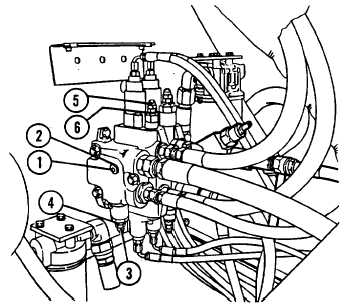
Hold adjusting screw in
position and tighten jam nut (6).
Install acorn nut (5).
4. ADJUST MAIN RELIEF VALVE
BETWEEN 2,750 AND 2,850 psi
a.
b.
c.
d.
Operate boom extend, retract,
hoist or lower function until
hydraulic oil is passing over
relief valve. Continue to hold
hydraulic lever in that position
so oil passes over relief valve
during relief valve adjustment.
Turn main relief valve adjusting
screw counterclockwise (out) until
pressure on gauge reads between
2,750 and 2,850 psi.
Release hydraulic function lever.
Hold adjusting screw in position
and tighten jam nut (4). Install
acorn nut (3).
5. STOP ENGINE, TM10-3930-660-10.
WARNING
Hydraulic oil in the system can be under
pressures over 3000 psi with the engine
OFF. ALWAYS relieve pressure in
hydraulic lines before attempting to
remove any component in the hydraulic
system. With engine OFF, starter switch
in RUN position, and MLRS attachment on
the ground, move control levers through
all operating positions several times to
relieve line pressure. Relieve pressure
in hydraulic oil tank by loosening
filler cap very slowly. Failure to
follow these precautions could result
i
n
6.
serious personal injury.
REMOVE PRESSURE GAUGE.
Unscrew pressure gauge from main
relief valve plug assembly port (2).
18-23
|