| |
TM10-3930-660-20
8-20.
FORK AUTOLEVELER CIRCUIT BOARD - TEST/REPLACE (Cont’d)
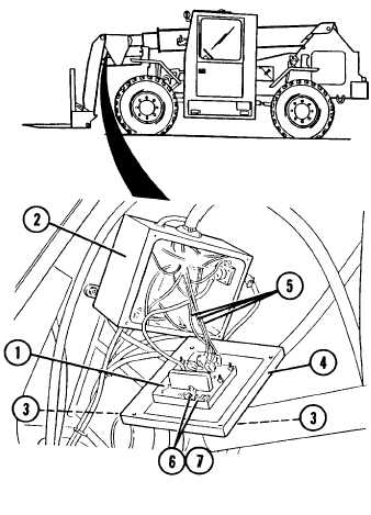
2. LOOSEN FOUR SCREWS (3) AND SEPARATE
COVER (4) FROM BOOM ELECTRICAL BOX
(2) TO PROVIDE ACCESS TO AUTOLEVELER
CIRCUIT BOARD (l).
CAUTION
Support cover (4) as required so that
weight of cover (4) and circuit board
(1) is not supported by electrical leads
(5) to board (l).
There are two LED indicators on the
autoleveler circuit board (l).
One is
labled “Hi A“ (6) and the other is
labeled “Hi B“ (7).
3. CHECK FOR PROPER ADJUSTMENT OF
AUTOLEVELR SWITCH.
a.
b.
c.
d.
Start engine.
Turn off autoleveler control in
cab.
Place level on forks.
Raise forks to approximately a +6
degree inclination and observe “Hi
A“ LED indicator (6).
The “Hi A“ LED indicator (6) should be
illuminated after forks are raised.
e. Turn on autoleveler control in cab
and observe “Hi A“ LED indicator
(6).
The “Hi A“ LED indicator (6) should
remain illuminated as forks are lowering
and go out when forks are level.
8-46
|