| |
TM10-3930-660-20
8-19.
ELECTRIC JOYSTICK AND HARNESS ASSEMBLY - TEST/REPLACE (Cont’d)
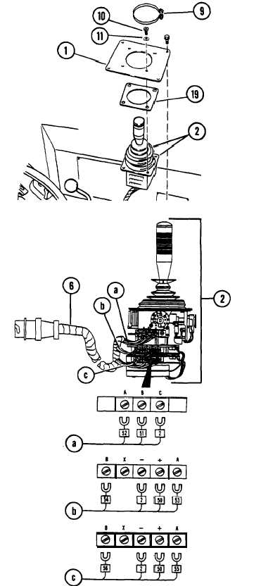
2. IF NECESSARY, REMOVE COVER PLATE (1)
FROM JOYSTICK (2).
a.
b.
c.
Remove clamp (9).
Remove four screws (10) and four
nylon washers (11) securing
joystick (2) and gasket (19) to
cover plate (l). Discard nylon
washers (11).
Separate joystick (2) from cover
plate (l).
Tag all leads as removed during steps 3a
through 3c. Note location of all leads
for use during installation. Refer to
figure at right as required.
3. IF NECESSARY, DISCONNECT JOYSTICK
HARNESS (6) FROM JOYSTICK (2).
a.
b.
c.
Disconnect leads 52, 51, and 2 (a)
from top terminal strip of
joystick (2).
Disconnect leads 54, 2, 50, and 53
(b) from middle terminal strip of
joystick (2).
Disconnect leads 56, 2, 50, and 55
(c) from bottom terminal strip of
joystick (2).
INSTALLATION
CAUTION
Connect all leads as described in steps
la through lc. Refer to figure at right
as necessary. Failure to properly
connect leads may result in serious
damage to joystick or electrical system.
1. IF REMOVED, CONNECT JOYSTICK HARNESS
(6) TO JOYSTICK (2).
a. Connect leads 52, 51, and 2 (a) to
top terminal strip of joystick (2).
b. Connect leads 54, 2, 50, and 53
(b) to middle terminal strip of
joystick (2).
c. Connect leads 56, 2, 50, and 55
(c) to bottom terminal strip of
joystick (2).
8-42
|