| |
TM10-3930-660-20
8-9 l
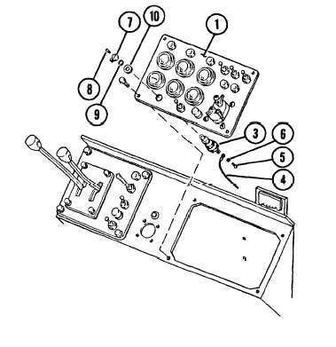
STARTER SWITCH - REPLACE (Cont’d)
2.
3.
TAG AND REMOVE ELECTRICAL LEADS (4)
FROM STARTER SWITCH (3).
a.
b.
Tag electrical leads (4) connected
to switch (3).
Remove five screws (5) and
lockwashers (6) securing
electrical leads (4). Remove
electrical leads (4) from switch
(3).
Discard lockwashers (6).
REMOVE STARTER SWITCH (3) FROM
INSTRUMENT PANEL (1).
Note orientation of starter switch (3)
and starter switch knob (7) for use
during installation.
a.
b.
c.
Remove screw (8) and knob (7)
from switch (3).
Remove retaining ring (9) and
nut (10) securing switch (3) to
instrument panel
Slide switch (3)
mounting hole on
(1).
INSTALLATION
(1).
out through
instrument panel
1. INSTALL STARTER SWITCH (3) TO
INSTRUMENT PANEL (1).
Position starter switch (3) and starter
switch knob (7) as noted during removal.
a.
b.
c.
8-22
Slide switch (3) in through
mounting hole on instrument panel
(1).
Secure switch (3) to instrument
panel (1) with nut (10) and
retaining ring (9).
Position knob (7) on switch (3).
and secure with screw (8).
2.
3.
CONNECT ELECTRICAL LEADS (4) TO
STARTER SWITCH (3) AS TAGGED.
a.
b.
Position electrical leads (4) on
switch (3) as tagged.
Secure electrical leads (4) to
switch (3) with five new lockwashers
(6) and five screws (5).
LOWER AND SECURE RIGHT-HAND
INSTRUMENT PANEL (1).
a.
Apply
(2) l
b.
Lower and align right-hand
instrument panel (1).
Loctite 242 to threads of capscrews
Secure right-hand instrument panel
(1) with four capscrews (2).
4. CONNECT NEGATIVE BATTERY CABLE,
PARA. 8-44.
|