| |
TM 10-3930-659-34
4-60. PIVOT PINS AND BUSHINGS REPLACEMENT (Con’t).
7.
Remove lubrication fitting (10) from upper pivot pin (7). Discard lubrication fitting.
8.
Remove capscrew (12) from engine frame (6).
NOTE
Perform steps 9 through 16 to fully separate loader frame from engine frame.
9.
Install suitable lifting device to loader frame (11). Raise suitable lifting device enough to support weight of loader
frame.
10.
Disconnect steering cylinders (see TM 10-3930-659-20).
11.
Disconnect STE/ICE turn signal/emergency flashers and blackout lights wiring harness (see TM 10-3930-659-20).
12.
Disconnect loader frame wiring harness (see TM 10-3930-659-20).
13.
Disconnect front brake hose (see TM 10-3930-659-20).
14.
Disconnect plate-to-loader frame bracket hoses (see TM 10-3930-659-20).
15.
Separate loader frame (11) from engine frame (6).
16.
Position wood cribbing under rear of loader frame (1 1).
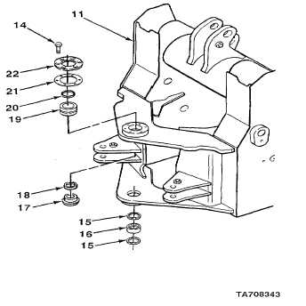
17.
Remove six screws (14), cover (22), four shims (21), and seal (20) from loader frame (1 1).Discard seal.
18.
Remove nut sleeve (17) and seal (18) from loader frame (11). Discard seal.
19.
Using puller kit, remove bearing (19) from loader frame (11).
20.
Remove two seals (15) and bushing (16) from loader frame (11). Discard seals.
4-227
|