| |
TM 10-3930-659-34
Section XIII. FRAME MAINTENANCE
4-60. PIVOT PINS AND BUSHINGS REPLACEMENT.
This task covers:
a.
Removal
b.
Installation
INITIAL SETUP:
Equipment Conditions:
Materials/Parts:
• Forklift truck parked on a smooth, level, hard surface
• Silicone compound (Item 16, Appendix B)
with wheels straight ahead (see TM 10-3930-
• Grease (Item 33, Appendix B)
659-10).
• One locknut
• Parking brake set (see TM 10-3930-659-10).
• Two lubrication fittings
• Boom lock raised (see TM 10-3930-659-20).
• Four seals
• Steering valve removed (see TM 10-3930-659-20).
• Front universal joints and support bearing removed
Personnel Required: Three
(see TM 10-3930-659-20).
References:
Tools/Test Equipment:
• LO 10-3930-659-12
• General mechanic's tool kit (Item 71, Appendix E)
• TM 10-3930-659-10
• Feeler gage (Item 28, Appendix E)
• TM 10-3930-659-20
• Hydraulic jack, 10 ton (Item 39, Appendix E)
• Hydraulic jack kit (Item 40, Appendix E)
• Torque wrench multiplier (Item 44, Appendix E)
• Puller kit (Item 50, Appendix E)
• Trestle, 7 ton (two) (Item 73, Appendix E)
• Socket wrench set (Item 78, Appendix E)
• Torque wrench, 0-600 lb.-ft. (Item 82, Appendix E)
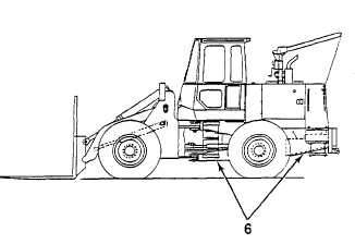
a. REMOVAL
1. Position two trestles under rear of engine frame
(6).
2. Position wood cribbing under front of engine
frame (6).
TA708341
4-225
|