| |
TM 10-3930-659-34
4-50.
AXLE HOUSING ASSEMBLY REPLACEMENT.
This Task Covers:
a.
Axle Bearing Adjustment Check
c.
Cleaning and Inspection
b.
Removal
d.
Installation
Initial Setup:
Equipment Conditions:
Materials/Parts:
•
Frame locking bar installed (see TM 10-3930-
•
Gasket forming compound (Item 13, Appendix B)
659-10).
•
Rags (Item 43, Appendix B)
•
Dry cleaning solvent (Item 47, Appendix B)
Tools/Test Equipment:
•
General mechanic's tool kit (Item 71, Appendix E)
Personnel Required: Two
•
Dial indicator (Item 19, Appendix E)
General Safety Instructions:
•
Hydraulic jack, 10 ton (Item 39, Appendix E)
•
Torque wrench, 0-600 Ib.-ft. (Item 82, Appendix E)
•
Dry cleaning solvent is flammable and must not be
used near open flame. Use only in a well-ventilated
References:
area.
•
TM 10-3930-659-10
a.
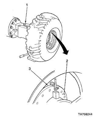
AXLE BEARING ADJUSTMENT CHECK
1.
Clean axle shaft flange (2) to bare metal in area
where dial indicator will be installed.
NOTE
•
Dial indicator probe must not contact
axle housing.
•
Dial indicator can be installed on
bottom of axle housing.
2.
Install dial indicator on axle shaft flange (2), as close
to axle housing (1) as possible, with dial indictor
probe touching inside of wheel rim (3).
3.
Position hydraulic jack under axle assembly and
raise axle assembly until wheel being checked is off
ground.
4.
Depress service brake pedal.
5.
Zero dial indicator and lower axle assembly to
ground.
6.
Record reading on dial indicator.
TA708244
4-182
|