| |
TM 10-3930-659-34
4-2.
CYLINDER HEAD VALVE LIFT CHECK (Con’t).
2.
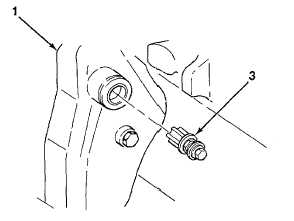
Install flywheel turning tool (3) on engine (1).
NOTE
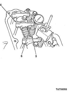
Cylinder head valve lift is checked the same way for all cylinder head
valves. One cylinder head valve is illustrated.
3.
Using flywheel turning tool (3), rotate flywheel until there is clearance between engine rocker arm (4) and cylinder
head valve (5).
4.
Install dial indicator on cylinder head valve (5) with
stylus against cylinder head valve rotator (6). Zero
dial indicator.
5.
Using flywheel turning tool (3), rotate flywheel and
note reading on dial indicator when clearance
between engine rocker arm (4) and cylinder head
valve (5) is fully opened. Intake cylinder head valve
lift measurement must be 0.4600.490 in.
(11.68412.446 mm) and exhaust cylinder head valve
lift measurement must be 0.4560.482 in.
(11.58212.243 mm). If measurements are not within
specification, inspect cylinder head valves (see
paragraph 4-6), engine rocker arm assembly and
pushrods (see paragraph 4-12), and tappets (see
paragraph 4-13).
6.
Remove dial indicator from cylinder head valve (5).
7.
Repeat steps 4 through 6 for remaining cylinder
head valves.
8.
Remove flywheel turning tool (3) from engine (1).
9.
Install plug (2) on engine (1).
FOLLOW-ON TASKS:
•
Install engine rocker arm cover (see TM 10-3930-659-20) 4-5
TA708058
4-5
|