| |
TM 10-3930-659-20
17-2.
FORK/BRAKE HYDRAULIC PUMP FLOW TEST (Con't).
NOTE
Perform steps 10 through 12 only if pump flow is not within specification.
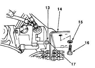
10.
Remove two screws (16), washers (15), and
plate (14) to gain access to cap (13) and
adjustment screw (17).
NOTE
Step 11 sets maximum displacement.
11.
Turn adjustment screw (17) into cap (13) until
one or two threads of cap are visible.
12.
Repeat step 9. If pump flow is not within specification, perform fork/brake hydraulic pump standby pressure test
(see paragraph 17-3).
13.
Shut down engine (see TM 10-3930-659-10).
14.
Install plate (14) with two washers (15) and screws (16).
15.
Repeat steps 1 and 2.
16.
Remove hydraulic tester outlet hose (5) from hydraulic reservoir (12).
17.
Install hydraulic reservoir filler cap (11) on hydraulic reservoir (12).
18.
Remove hydraulic tester inlet hose (7) from adapter (10).
19.
Remove plug (9) from hose (8).
20.
Install hose (8) on adapter (10).
FOLLOW-ON TASKS:
•
Install right transmission side guard (see paragraph 14-7).
•
Install right side cab skirt (see paragraph 14-6).
•
Remove frame locking bar (see TM 10-3930-659-10).
TA707615
17-9
|