| |
TM 10-3930-659-20
6-38.
WARNING BUZZER REPLACEMENT.
This task covers:
a.
Removal
b.
Installation
INITIAL SETUP:
Equipment Conditions:
Tools/Test Equipment:
• Battery disconnect switch in OFF position (see
•
General mechanic's tool kit (Item 44, Appendix F)
TM 10-3930-659-10).
References:
• TM 10-3930-659-10
a.
REMOVAL
1.
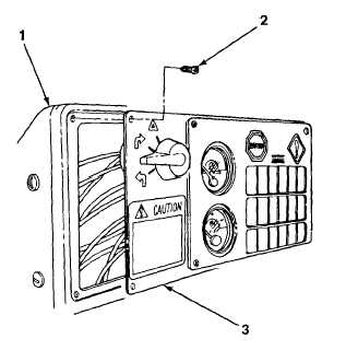
Remove four screws (2) and lift dash plate (3)
from dash housing (1).
2.
Disconnect warning buzzer connector (5) from fault monitor and dash wiring harness connector (4).
3.
Turn warning buzzer (6) counterclockwise and remove from fault monitor console (7).
TA707823
6-140
|