| |
TM 10-3930-659-20
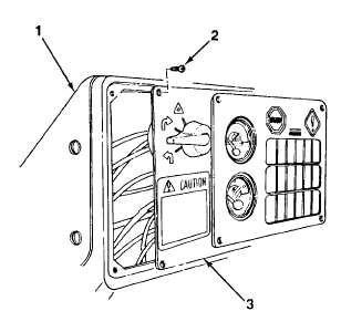
6-6.
FAULT MONITOR BULB REPLACEMENT.
This task covers:
a.
Removal
b.
Installation
INITIAL SETUP:
Equipment Conditions:
Materials/Parts:
• Battery disconnect switch in OFF position (see
•
One gasket
TM 10-3930-659-10).
References:
Tools/Test Equipment:
• TM 10-3930-659-10
• General mechanic's tool kit (Item 44, Appendix F)
a.
REMOVAL
1.
Remove four screws (2) and lift dash plate (3
from dash housing (1).
NOTE
Fault monitor console has three fault monitor modules. Determine location of
bulb needing replacement and remove only that fault monitor module.
2.
Remove three screws (8), fault monitor module (4), and gasket (5) from fault monitor console (6). Discard
gasket.
NOTE
Each fault monitor module has six bulbs. Bulbs are removed by pulling
straight out from fault monitor module.
3.
Remove bulb (7) from fault monitor module (4).
TA707717
6-24
|