| |
TM 10-3930-659-20
4-4.
GENERAL (Con't).
c.
Refer to TM 9-4910-571-12&P for STE/ICE-R set-up, operation, and fault isolation procedures. This manual
outlines general tests and maintenance procedures to help you keep the STE/ICE-R working properly. Refer to Table 4-4
for the M544E Forklift Truck test card.
4-5.
DESCRIPTION AND OPERATION.
The STE/ICE-R is portable and operates on the forklift truck's 24-volt system. It consists of a Vehicle Test Meter
(VTM), a Transducer Kit (TK), five electrical cables, a transit case, and technical publications. Refer to the manual
provided with the STE/ICE-R for VTM and TK descriptions and operating information.
4-6.
TEST PROCEDURES.
a.
The VTM provides the method to test the forklift truck's electrical and mechanical components. Readings
are either GO or NO-GO (pass/fail) indications or digital displays in units (psi, rpm, volts, Vdc, ohms, amps,
etc.).
b.
GO and NO-GO Chain sequences are presented in Tables 4-5, 4-6, and 4-7 as illustrated flowcharts, with
test branching controlled by YES and NO decisions. A YES response usually leads to the next test; a NO
response directs the technician to NO-GO testing and corrective actions.
c.
When the VTM interfaces with the forklift truck through the Diagnostic Connector Assembly (DCA), the test
is referred to as DCA Mode testing. When the VTM interfaces with the forklift truck through the use of the
Transducer Kit (TK), the test Is referred to as TK Mode testing. DCA and TK Mode testing can be used at
the same time.
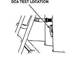
d.
The DCA is mounted on the front of the right side console near the cab floor and is accessible from the
operator's seat.
TA707954
4-44
|