| |
TM 10-3930-653-14&P
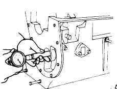
(2) Measuring lubrication
(oil) clearance
Measure the inside diameter of each bushing with a
bore gauge. If lubrication (oil) clearance exceeds the
prescribed limit, replace the bushing.
Fig. 4-69. Measuring Bushing l.D.
Correct to within
Service (clear
ance) limit
Lubrica-
tion (oil)
Front
& rear
0.025 to 0.051
(0.0010 to 0.0020)
0.1(00039)
clearane
Center
0.038 to 0.062
mm (in)
(0.0015 to 0.0024)
0.15 (0.0059)
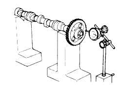
(6) TIMING SPROCKET
(1) Inspecting cam gear for wobble
With the camshaft and camshaft sprocket placed on
V-blocks. measure camshaft sprocket wobble, and
correct or replace the cam gear if wobble exceeds 0.1
mm (0.0039 in). Also inspect the sprocket for broken or
damaged teeth and for wear or damage on the boss
surface. If excessively worn or damaged, replace with a
new gear.
Fig. 4-70. Checking Camshaft Sprocket Wobble
(7) FRONT COVER AND
HYDRAULIC PUMP
CHAIN COVER
Inspect the installation (mating) surface and oil seal.
If damaged or faulty, correct or replace as required.
4-2-4-12.
VALVE ROCKER
MECHANISM
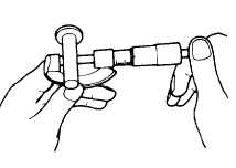
(1) VALVE LIFTERS
Inspect the periphery of the valve lifter and the cam
contact surface. Replace the valve lifter if excessively
worn, damaged or fused. Also check for fit in the
cylinder block and replace if fit is not proper. Fit should
be such that the lifter, with oil applied, lowers slowly and
naturally In the hole in the cylinder block.
Fig. 4-71. Measuring Diameter of Valve Lifter
Correct to
Service limit
within
Fit (clearance) of
valve lifter and
0.016 to 0.052
0.1 (0.0039)
cylinder block
(0.0006 to 0.0020)
hole
mm (in)
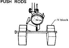
Fig. 4-72. Measuring Push Rod Bending
4 - 40
|