| |
TM 10-3930-653-14&P
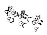
Fig. 4-64. Main Bearing Caps and Bearings
(2) Measuring lubrication
(oil) clearance
(1) Measure lubrication (oil) clearance with a width
gauge (plastigage). For applicable instructions, refer to
paragraph on lubrication (oil) clearance measurement for
connecting rod bushing.
Tightening torque:
Bearing cap
8.5 to 9.5 kg-m
(61 to 69 ft-lb)
(2) If lubrication (oil) clearance exceeds prescribed limit,
select an appropriate replacement part from service
parts, checking crank-journal diameter.
Service (clearance)
Correct to within
limit
Main bearing
lubrication
0.02 to 0.062
0.1 (0.0039)
(oil) clea-
(0.0008 to 0.0024)
rance
mm (In)
Main bearing bushing specifications
Undersize mm (in)
Crank journal dia. mm (in)
62.692 to 62.705
0.25 (0.0098)
(2.4682 to 2.4687)
62.422 to 62.455
0.50 (0.0197)
2.4576 to 2.45)
62.192 to 62.205
0.75 (0.0295)
(2.4485 to 2.4490)
61.942 to 61.955
1.00 (0.0394)
(2.4387 to 2.4392)
4-2-4-11.
CAMSHAFT
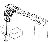
(1) CHECKING CAMSHAFT FOR
BENDING
Measure the camshaft for bending and, If beyond
prescribed bend limit, correct with a press or replace with
a new camshaft. For measurement, support the
camshaft on V-blocks at each end, as shown in Fig. 2-
53 (1/2 of the maxi-mum value shown on the dial gauge
is the amount of bend).
Fig. 4-65. Measuring Camshaft Bending
Service (bend)
Correct to within
limit
Camshaft
bending
0.02 (0.0008)
0.05 (0.0020)
mm (in)
4 - 38
|