| |
TM 10-3930-653-14&P
(3) Remove cap. and measure width of gauge (using a
scale for measurement) at widest point. If the difference
between the maximum and width of pressed gauge
exceeds 0.03 mm (0.0012 in), check journal for out-of-
roundness.
(4) If lubrication (oil) clearance exceeds pre-scribed
limit. replace parts as required from service parts Under
no circumstances should any attempt be made to adjust
lubrication (oil) clearance by using emery cloth on the
portion to which the cap is applied, by using shims. or by
scraping or filing down bushing.
Connecting rod bushing specifications
Under size
Tickness at top of I
Crank pin dia.
mm (in)
bushing mm (in)
mm (in)
0 25
1 623 to 1 631
51.711 to 51.724
(0.098)
(00639 to 0.0642)
(2.0359 to 2.0364)
0 50
1.748 to 1.756
51.461 to 51.474
(0.0197)
(0.0688 to0.0691)
(2.0260 to 2.0265)
4-2-4-9.
CRANKSHAFT
(1) INSPECTION CRANKSHAFT
WARNING
Dry cleaning solvent P-D-680 is toxic
and flammable. Wear protective
goggles and gloves and use only in a
well ventilated area. Avoid contact
with skin, eyes, and clothes and don’t
breathe vapors. Do not use near
open flame or excessive heat. If you
become dizzy while cleaning with
solvent, get fresh air immediately and
get medical aid. If contact with skin
or clothing is made, flush with water.
If contact with eyes is made, wash
your eyes with water and get medical
aid immediately.
WARNING
Compressed air used for cleaning
purposes will not exceed 30 PSI. Use
only with effective chip guarding and
personal
protective
equipment
(goggles/shield, gloves, etc.).
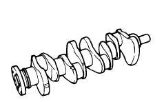
Thoroughly clean the crankshaft and inspect the pin
and journal counterweights (balance weights) for cracks
or damage, make sure that the oil seal contact surface is
satisfactory and that the pins and journals are not
scarred or damaged.
Fig. 4-60. Inspecting Crankshaft
(2) JOURNAL AND PIN
DIAMETER MEASUREMENT
Measure journal and pin diameters for wear using a
micrometer. If worn beyond the normal service (wear)
limit or if out-of-round, correct them to an appropriate
undersize (For finishing dimensions refer to paragraphs
on main bearing and connecting rod bushings) Measure
at a total of 8 positions: 2 positions in the center parts of
the pins and journals In which there are no holes, 2
positions at both ends. and 2 positions at right angles to
both ends. Eccentric wear Is determined as being the
difference
between
maximum
and
minimum
measurement values.
Fig. 4-61. Measuring Journal and Pin Diameter
Correct to
Service lout-of
within
round/taper)
limit
Degree of out-of-
round and taper
0.01 (0.0004)
0.03 (0.0012)
mm (in)
4 - 36
|