| |
TM 10-3930-653-14&P
4-2-4-3.
CYLINDER HEAD
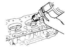
(1) REMOVING CARBON
Remove carbon from the combustion chamber of the
cylinder head and from the side surface on which the
manifold is installed and check for scars or damage.
Fig. 4-36. Cleaning Cylinder Head
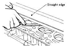
(2) MEASURING CYLINDER
HEAD FOR WARPAGE
Measure
the
cylinder
head
surface
for
both
longitudinal
and
transverse
warpage.
If
uneven
(warpage exceeds prescribed limit). correct the surfaces
with a mill grinder.
Fig. 4-37. Measuring Cylinder Head
Fire Deck (Block Contact Surface)
for Warpage
Surface flatness
Less than
mm (in)
0.1 (0.004)
Grinding limit
mm (in)
2.0(0.08)
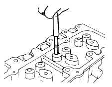
(3) REAMING VALVE GUIDES
Measure valve stem and valve guide clearance If
clearance exceeds prescribed limit. ream out the valve
guide and install valves with oversized stems. Two types
are provided (for intake and exhaust valves): .20mm and
.40mm oversizes.
Fig. 4-38. Reaming Valve Guide
Standard
Service limit
clearance
Clearance
0.028 to
(Intake)
0.030
0.10
Valve stem/
(0.0011 to
(0.0039)
valve guide
0.0012)
clearance
0.058 to
mm (in)
(Exhaust)
0.060
0.15
(0.0023 to
(0.0059)
0.0024)
Intake valve stem dia.
mm (in)
Exhaust valve stem dia
mm (in).
8.657 to 8.670
8.627 to 8.640
STD
(0.3408 to 0.3413)
(0.3396 to 0.3402)
8.857 to 8.870
8.827 to 8.840
20
(0.3487 to 0.3492)
(0.3475 to 0.3480)
9.057 to 9.070
9.027 to 9.040
40
(0.3566 to 0.3571)
(0.3554 to 0.3559)
4 - 28
|