| |
TM 10-3930-653-14&P
4-1-3 ENGINE TUNE-UP
4-1-3-1. DESCRIPTION
To restore power and performance that has been lost
through wear, corrosion, or deterioration, periodic
maintenance (engine tune-up) is necessary.
It is Important that the engine tune-up be done
accurately according to the maintenance schedule
shown in section four ( 4) of this manual.
This chapter describes actual operating procedures
for the maintenance operation of items to be inspected.
4-1-3-2. BASIC MECHANICAL
SYSTEM
(1)
RETIGHTENING CYLINDER HEAD BOLTS,
MANIFOLD BOLTS AND NUTS
Cylinder head bolts and valve rocker shaft bracket
bolts:
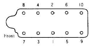
When the engine is cold, tightening should be made
In several steps and in the sequence shown in Fig. 1-1.
starting with the center and moving toward the ends.
Fig. 4-1. Tightening Sequence of
Cylinder Head Bolts.
Tightening torque:
Cylinder head bolts
8.0 to 9.5 kg-m
(59 to 69 ft-lb)
When the engine is warm, tighten the bolts and nuts
to a torque of 0.5 kg-m ( 3.6 ft-lb) higher than the
specifications shown above
Intake and exhaust manifold bolts and nuts should be
tightened to the specified torque, shown below.
Tightening torque:
Intake and exhaust manifold
1.4 to ;.8 kg-m
(10 to 13 ft-lb)
(2)
ADJUSTING INTAKE AND EXHAUST VALVE
CLEARANCES
Valve clearance adjustment should be made while
engine is not running.
To adjust. proceed as follows
(1)
Start engine and run it until it is heated to
operating temperature. or at least, more than 80 C (176°
F). then stop engine.
(2)
Rotate crankshaft to bring No. 1 cylinder to top
dead center on its compression stroke. ( Number 1
cylinder is the one closest to the fan).
( 3)
Remove al e rocker cover to gain access to
valve operating mechanism.
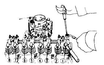
Adjust valve clearance at the following four
points while engine is still hot.
a. Exhaust valve of No. 1 cylinder
(l)
b. Intake valve of No. 1 cylinder
(2)
c. Intake valve of No. ’2 cylinder
(3)
d. Exhaust valve of No. 3 cylinder
(5)
Note: Encircled numbers agree with
those in accompanying sketch.
Fig. 4-2. Adjusting Valve Clearance.
(4)
Rotate crankshaft one complete turn so that the
No. 4 piston is on top dead center of its compression
stroke. Adjust the following valves:
e. Exhaust valve of No. 2 cylinder
(4)
f. Intake valve of No. 3 cylinder
(6)
g. Intake valve of No. 4 cylinder
(7)
h. Exhaust valve of No. 4 cylinder
(8)
4 - 8
|