| |
TM 10-3930-653-14&P
(c)
Drawing out of Plunger (See Fig. 9-3.) With the
neutral passage closed, the oil pushes up the
load check valve, passing through the parallel
feeder, and flows to the cylinder port "A". The
returning oil from the cylinder port "B" flows
through the low-pressure passage to the tank.
The plunger is restored to the neutral position by
the return spring.
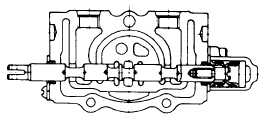
(2)
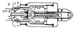
Operation of Relief Valve
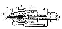
The relief valve is located between the
cylinder port "HP" and the low-pressure passage
"LP". The oil flows through the poppet "C" and
affects the two areas "A" and "B" which are
different in diameter, so that the check valve
poppet "K" and the relief valve poppet "D" are
securely seated. (See Fig. 9-4.)
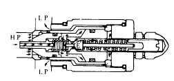
When the pressure in the cylinder port "HP"
reaches the setting pressure of the pilot poppet
spring, the pilot poppet "E" opens. The oil
passes around the poppet, flowing through the
drilled hole to the lowpressure side "LP". (See
Fig. 9-5.)
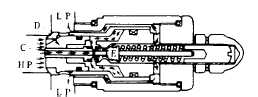
As the pilot poppet "E" is opened, the
pressure behind the poppet "C" drops, so that
the poppet "C" is moved to seat of the pilot
poppet "E".
As a result of this, the oil flowing behind the
relief valve poppet "D" is cut off and the pressure
at the inner side is reduced. (See Fig. 9-6.)
As compared to the pressure at the cylinder
port "HP" side, the inner pressure becomes
unbalanced, causing the relief valve poppet "D"
to open and thereby sending the oil directly to
the low-pressure passage "LP". (See Fig. 9-7.)
Fig. 4-469.
Fig. 4-470.
Fig. 4-471.
Fig. 4-472.
Fig. 4-473.
4-237
|