| |
TM 10-3930-653-14&P
At the drive shaft side, an oil seal is press-fitted into the pump body to provide oil tightness performance. Oil
tightness between the pump body and the pump cover is secured with a specially shaped packing.
CONTROL VALVE
The control valve consists of five(5) valve housings,three(3)plungers and one (1) relief valve. Each plunger and
plunger housing are sandwiched by the inlet housing and outlet housing, which are all assembled with three stud bolts and
nuts. The inlet housing contains the cartridge type relief valve.
(1)
Plunger Operation
(a)
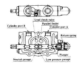
Neutral Position Oil discharged from the pump returns through the neutral passage to the tank.
Fig. 4-467.
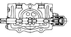
(b)
Pushing in of Plunger
The neutral passages are closed and the oil passes
through the parallel feeder and flows, pushing up the
load check valve into the cylinder port "B". The returning
oil from the cylinder port "A" flows through the low-
pressure passage to the tank. The plunger is restored to
the neutral position by the return spring.
Fig. 4-468.
4-236
|