| |
TM 10-3930-653-14&P
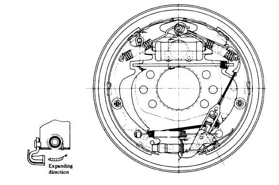
OPERATION TEST OF AUTOMATIC CLEARANCE ADJUSTER
(1)
Make the brake shoe diameter nearly the specified mounting size, and pull the adjuster lever with your finger
along the arrow mark as shown in the illustration given below to turn the adjuster gear. When removing your
finger. the adjuster lever returns to its original position without rotation of the adjuster gear.
NOTE : Even if the adjuster gear turns back along with the adjuster lever motion when removing your
finger, the adjuster will operate normally, when braked in reverse travel, after it has been mounted on the
truck.
(2)
If the adjuster fails to do the above operation when pulling the adjuster, proceed with follwoing inspection.
(a)
Make sure that the adjuster lever, adjuster, adjuster spring, adjuster cable and shoe-to-shoe spring are
securely installed.
(b)
Check to see if the distance between the adjuster gear and the adjuster lever is 6 + 2 mm (0.15 + 0.135 in).
See Fig. 8-25. If unsatisfactory, replace the part. Also check that the adjuster lever is in proper mesh with
the gear.
(c)
Check the shoe-to-shoe spring and adjuster for deterioration, adjuster for proper rotation, gears for wear,
and adjuster lever and its gear for damage. If unsatisfactory, replace.
Fig. 4-466.
4-234
|