| |
TM 10-3930-653-14&P
(8)
Install the shoe guide plate on the anchor pin,
and then install the shoe return spring on it. The
primary side should be first worked on then
proceed to the secondary side.
(9)
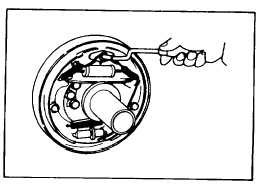
Install the shoe-to-shoe spring, adjuster, adjuster
spring and adjuster lever, paying attengion to the
following points.
(1)
The
screw
direction
and
mounting
direction of the adjuster, i.e. left-hand
screw for left-side brake and right-hand
screw for right-side brake.
Fig. 4-463.
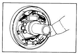
Fig. 4-464.
(2)
Adjuster spring direction. (Do not allow the adjuster gear teeth to contact with the spring.)
(3)
The shoe-to-shoe spring should be installed with the longer hook at the adjuster lever side.
(4)
After assembly, make sure that the adjuster lever end is in contact with the adjuster gear teeth.
(10)
Install brake line on the wheel cylinder.
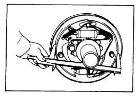
(11)
Measure the inner diameter of brake drum
and adjust brake shoe outer diameter to drum
inner diameter 1.0 mm (0.04 in) by using the
adjuster.
Fig. 4-465.
4-233
|