| |
TM 10-3930-653-14&P
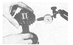
(3) Install gears onto respective shafts and measure clearance between splines of them in rotational direction. If splines
are excessively worn, replace gear.
Note :
When making checks, gears should be installed in position on each shaft. If gears are not installed
correctly, a wrong measurement will be obtained.
Unit: mm(in)
Checking Item
Standard Value
Service Limit
Clearance between output
0 1-0 2
shaft and output gear spline
(0.004-0.008)
--
in rotational direction
Clearance between idle gear
0.1-0.2
shaft and reverse idle gear in
(0.004-0.008)
--
rotational direction
Clearance between pump drive
0.073-0.156
gear and pump wheel boss
(0.003-0.006)
--
splines in rotational direction
, I
CASE COVER INSPECTION
(1)
Check switch plate of direction change rod for
wear, and if unsatisfactory, replace.
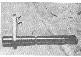
(2)
Measure valve control lever end diameter, and
check for wear or damage. If any defect is found,
replace.
Unit: mm(in)
Checking Item
Standard Value
Service Limit
Valve control lever end
13.8-14.0
diameter
(0.543-0.55)
--
Fig. 4-319. Checking Gear Splines
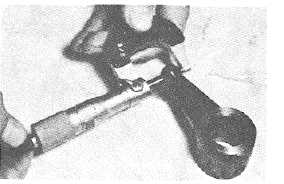
Fig. 4-320.
Fig. 4-321. Measuring Valve Control Lever End
Diameter
4-171
|