| |
TM 10-3930-653-14&P
CHARGING PUMP DISASSEMBLY
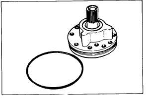
(1) Remove O-ring from the circumference of the case.
Fig. 4-260.
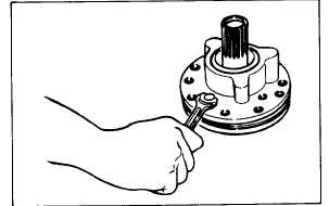
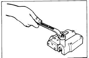
(2) Remove two assembling bolts.
Fig. 4-261.
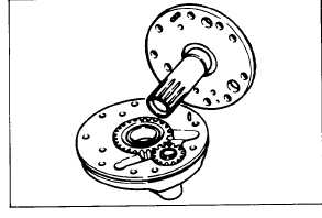
(3) Separate case from cover.
Fig. 4-263.
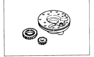
(4) Remove gears from case.
Fig. 4-264.
CONTROL VALVE DISASSEMBLY
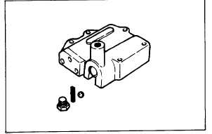
(1) Remove detent plug.
Fig. 4-262.
(2) Remove detent spring and steel ball.
Fig. 4-265.
4-155
|