| |
TM 10-3930-653-14&P
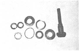
(3) Using a suitable press, remove tapered bearing and
oil seal from output shaft.
Fig. 4-250.
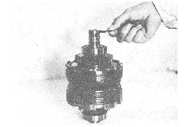
HYDRAULIC CLUTCH DISASSEMBLY
(1) Remove three seal rings from shaft.
Fig. 4-251.
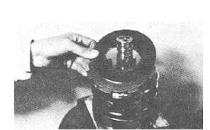
(2) Using a suitable puller, remove forward gear along
with bearing.
Fig. 4-252.
WARNING
Exercise care when removing snap
rings.
(3) Remove snap ring.
Fig. 4-253.
(4) Remove end plate and clutch disks. (On Model 424-
25 and 426-25, conical plate is also to be removed.)
Fig. 4-254.
4-153
|