| |
TM 10-3930-653-14&P
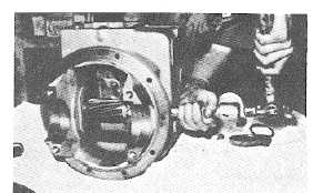
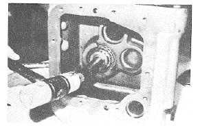
(13) Remove reduction gear shaft in the direction shown
In Fig. 2-55.
Fig. 4-244.
WARNING
Exercise .-are when removing snap
rings.
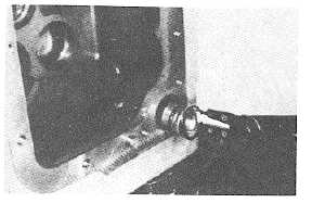
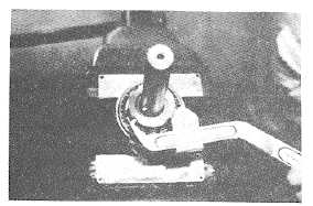
(14) Remove snap ring from oil strainer and then oil
strainer.
Fig. 4-245.
OUTPUT SHAFT DISASSEMBLY
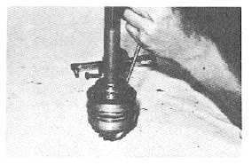
(1) Straighten tangs of lock washer.
Fig. 4-246.
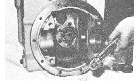
(15) Remove output shaft set plate.
Fig. 4-247.
(16) Remove output shaft In the direction shown in Fig.
2-58.
Fig. 4-248.
(2) Remove bearing nut.
Fig. 4-249.
4-152
|