| |
TM 10-3930-653-14&P
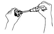
Fig. 4-215. Removing Cam
(2) ASSEMBLY
Assembly can be made in reverse sequence of
disassembly.
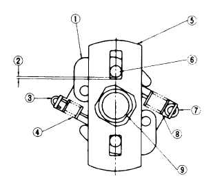
1. Governor weight
6. Weight pin
2. Clearance for start and
7. Circular hook
end of advancing angle
8. Governor spring (A)
3. Rectangular hook
9. Rotor positioning tip
4. Governor spring (B)
5. Cam plate
Fig. 4-216. Setting Governor Spring and Cam
4-118
|