| |
TM 10-3930-653-14&P
when installed on engine. The starting motor should also
be subjected to a test when the cause of abnormal
operation is to be determined. A brief outline of test is
given below.
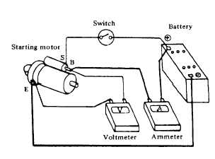
No-load test
Connect the starting motor in series with a specified
(12 volts) battery and an ammeter capable of indicating
1.000 amperes.
Fig. 4-168. No-Load Test
(2)
DIAGNOSES OF TEST
(1)
Low speed with no-load and high current draw may
result from the following causes.
a.
Tight. dirty or worn bearings.
b.
Bent armature shaft or loose field probe.
c.
Shorted armature.
Check armature further.
d.
A grounded armature or field:
(a.) Remove input terminal.
(b.) Raise two negative side brushes from commutator.
(c.)
Using a circuit tester. place one probe onto yoke.
(d.) If tester indicates continuity. raise the other two
brushes and check the field and armature separately to
determine whether the field or armature is grounded.
(2)
Failure to operate with high current draw may result
from the following items.
a.
A grounded or open field coil:
Inspect connection and trace circuit with a circuit
tester.
b.
Armature coil does not operate:
Inspect commutator for excessive burning. In this
case. an arc may occur on malfunctioning commutator
when motor is operated with no-load.
c.
Burned out commutator bar:
Weak brush spring tension, broken brush spring,
rubber bush, thrust out of mica in commutator or a loose
contact between brush and commutator would cause
burned-out commutator bar.
(3)
Low current draw and low no-load speed Ĺ would
cause high internal resistance due to loose connections,
faulty leads, dirty commutator and causes listed in item
2-C.
(3)
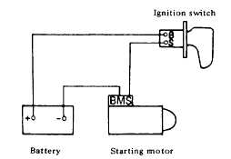
MAGNETIC SWITCH
ASSEMBLY TEST
Fig. 4-169. Magnetic Switch Assembly Test
If starting motor check is "OK," check magnetic
switch assembly. Connect cables between "negative"
battery terminal and starting motor "M" terminal,
"positive" battery terminal and starting motor "S" terminal
connecting ignition switch in series as shown in Fig. 7-
20.
With ignition switch on, measure the gap "Q"
between pinion front edge and pinion stopper.
4-100
|