| |
TM 10-3930-653-14&P
(7)
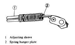
Take out cam from shaft together with cam band,
spring, and adjusting sleeve, paying attention not to
deform cam band.
Note
When disassembling further, count
active coils of spring, and keep in
mind screwed condition of spring
hanger block and adjusting sleeve
which are located at both ends of
spring,
and
relative
position
of
groove of adjusting sleeve and cam
band. These steps will serve to
facilitate adjustment after assembly.
Fig. 4-138. Mounted Condition of Spring
(8)
Remove adjusting sleeve, cam spring and cam
band.
(2)
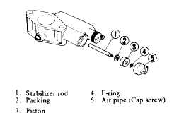
STABILIZER PISTON
Cap screw and air pipe can be taken out as a unit.
Then, remove piston.
Fig. 4-139. Stabilizer Piston Disassembled
(3)
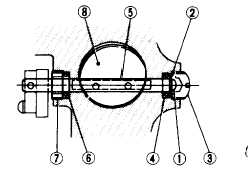
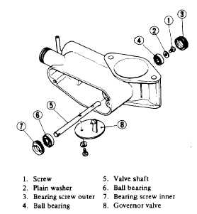
GOVERNOR VALVE
Fig. 4-140. Relative Position of Governor Valve, etc.
Fig. 4-141. Governor Valve, etc. Disassembled
(1)
Remove governor valve.
(2)
Remove bearing screw outer.
(3)
Remove screw and washer securing valve shaft.
(4)
Slightly tap valve shaft at cam chamber.
side, and it can be driven out together with ball bearing.
(5)
Turn bearing screw inner at cam chamber side
counterclockwise, and remove ball bearing at cam-
chamber side.
4-78
|