| |
TM 10-3930-653-14&P
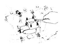
Fig. 4-134. Removing Pneumatic Governor
(9)
Installation is in the reverse order of removal.
4-6-3-5. DISASSEMBLY
Do not disassemble governor except when it is
necessary. Particularly avoid disassembling cam and
cam plate because their setting is very delicate.
(1)
CAM AND CAM SPRING
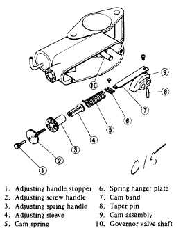
Fig. 4-135. Cam and Cam Spring Disassembled
(1)
Take off cover of cam chamber.
Note
Place a matching mark as shown in
Fig. 6-17 with paint across adjusting
screw
handle,
adjusting
spring
handle, and body in order to facilitate
adjustment after assembly.
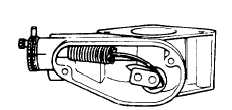
Fig. 4-136. Scribing a Mark
(2)
Remove adjusting handle stopper after un fastening
its lock wire.
(3)
Screw out adjusting screw handle by turning it
counterclockwise.
Note
In order to facilitate adjustment after
assembly,
hold
adjusting
spring
handle with one hand to prevent if
from rotating together, and loosen
adjusting
screw
handle.
Note
number of revolutions by aid of
mating mark before it comes off.
(4)
Pull off adjusting spring handle.
(5)
Remove cam stopper bolt by loosening lock nut.
(6)
Push out taper pin which is securing cam on shaft
using a screwdriver from underside, and then pull it out
from upper side.
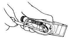
Fig. 4-137. Removing Taper Pin
4-77
|