| |
TM 10-3930-653-14&P
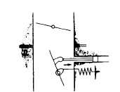
Fig. 4-126.
Figs. 6-8 and 6-9 show the operation of the
governor valve under various operating conditions of the
engine. In these figures, the force to open the valve
exerted by the cam and cam spring is indicated by a
dotted arrow, the force to close the valve produced by
the pressure difference between both sides of the valve
is shown by a white arrow, and that effected by the
stabilizer piston is expressed by a black arrow; and the
size of these arrows indicates the strength of force under
each condition.
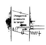
Fig. 4-127.
Fig. 4-128. Negative Pressure is Large
a.
When the engine is stalled.
The force to close the governor valve is absent, so it
is fully opened by the action of the cam spring.
b.
During idling.
Owing to a large negative pressure below the
throttle valve, the stabilizer piston tends to be sucked
out, causing the governor valve to be almost closed.
c.
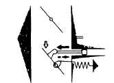
When the carburetor throttle valve is partially
opened.
When the engine is rotating at low speed, the
pressure difference between both sides of the governor
valve is small, exertising only a small force on the
stabilizer piston, so the governor valve is kept fairly open.
With the increase of engine speed, the pressure
difference between both sides of the governor valve as
well as the force on the stabilizer piston increases,
causing the valve to close.
Fig. 4-129.
4-75
|