 |
|||
|
|
|||
|
|
|||
| ||||||||||
|
|
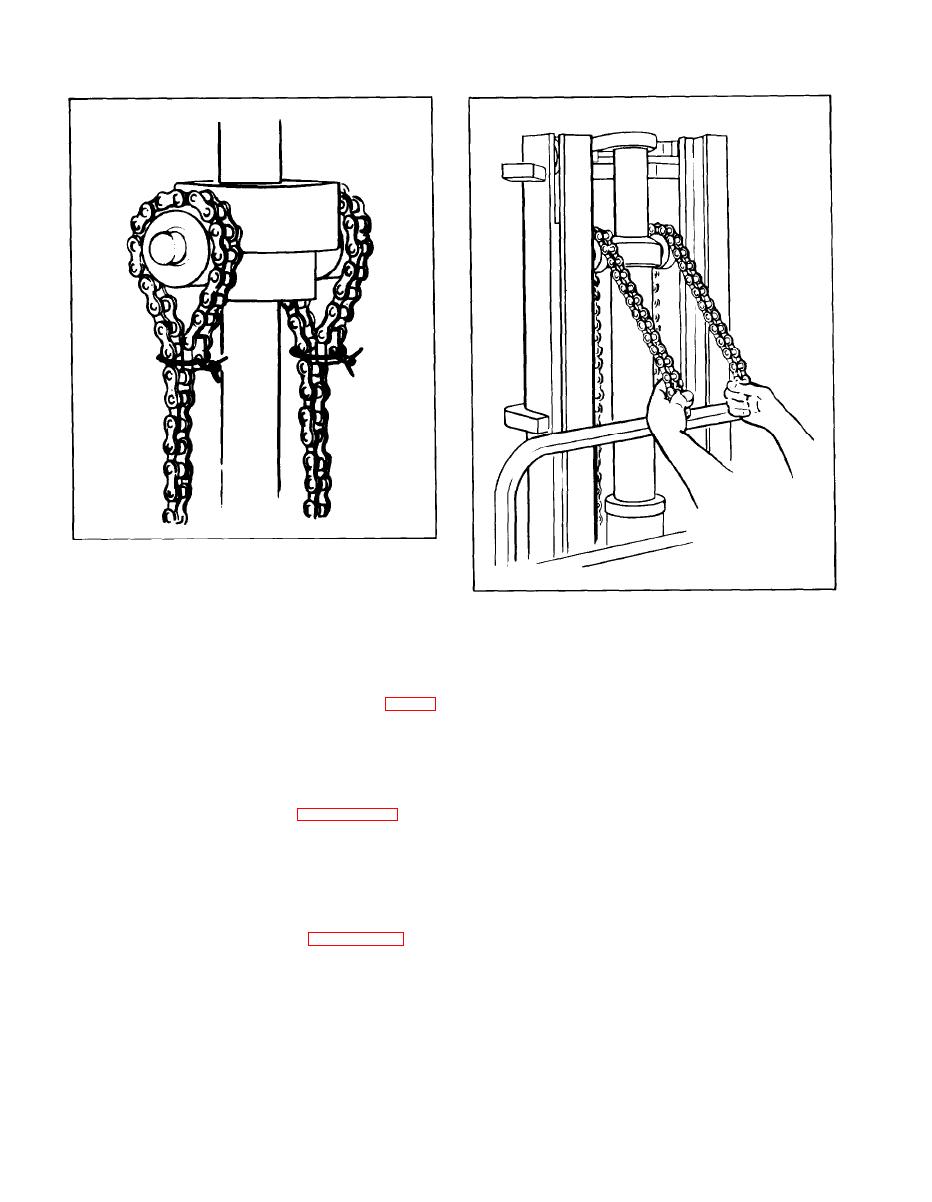 Figure 5-143. Securing Chains
Figure 5-144. Seating Piston Head
time, and replace each pin with a 3/8 inch diameter
x 2 inch long bolt.
upper carriage rollers, so that the carriage will be
d. Raise the carriage off the upright beam. Place
entirely free of the upright.
the beam on the floor so that the lift forks will rest
upon it when the carriage is lowered. (See figure
j . Remove wheel blocking, release hand brake,
6142.)
and back truck away from the carriage.
e. Tilt the upright forward as far as it will go, and
5-140. CLEANING AND INSPECTION.
place a pallet or other weight across the forks so
that the carriage will not tip backwards when it is
a. Clean components with a clean Stoddard type
removed from the upright. (See figure 5-142.)
solvent and dry thoroughly.
f. Remove the two 3/8 inch bolts holding chain
b . Inspect carriage and rollers for evidence of
a n c h o r in place. Pull the chain ends out of the
wear or physical damage.
anchor brackets.
c . Check for cracks, particularly at welds, and
g. Secure loose ends of the lift chain around the
sprockets by wiring as shown in figure 6-143.
evidence of permanent distortion or bending due
to overloading or impact.
h. Grasp lift chains near piston head and raise
5 - 1 4 1 . MINOR REPAIR.
piston to the full up position.
a. Replacedamaged or bent forks and worn rollers.
i. Raise inner rail of the upright until it clears the
5-100
|
|
Privacy Statement - Press Release - Copyright Information. - Contact Us |
