 |
|||
|
|
|||
|
Page Title:
Figure 5-134. Steering Cylinder Seals |
|
||
| ||||||||||
|
|
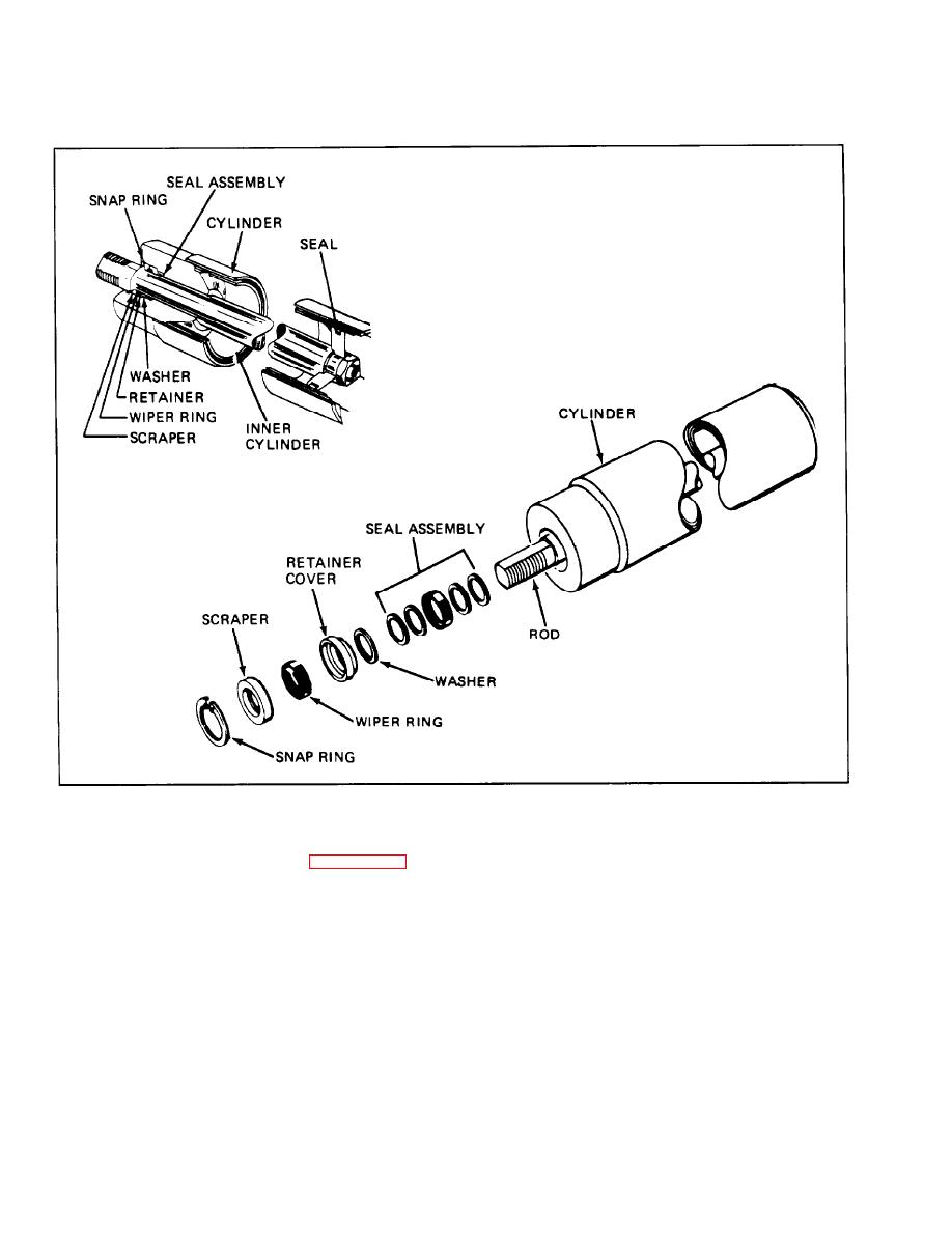 Figure 5-134. Steering Cylinder Seals
housing to the valve and remove self-locking nut
5-113. STEERING VALVE. (See figure 5-135.)
f r o m spool capscrew. Remove capscrew, washer
a n d control ball stud sleeve. Then lift the two
5 - 1 1 4 . DISASSEMBLY
centering spring retaining washers, centering spring
and spacer from the valve body. Remove O-rings
a. Hold control ball stud housing and valve
from valve body and from the spool.
assembly in a vise, by lightly clamping valve body.
Use care not to distort spool bore in valve body.
d. Remove the check valve, O-ring, and ball from
the valve body to complete the disassembly.
b. Remove control valve dust cover and remove
the wire snap ring which locks the control ball stud
5 - 1 1 5 . INSPECTION.
sleeve plug and remove plug. Remove control ball
stud, two ball stud seats, spring washer and spacer.
a. Discard all O-rings and seals and replace with
new upon reassembly.
c. Remove the bolts securing the ball stud
5-88
|
|
Privacy Statement - Press Release - Copyright Information. - Contact Us |
