 |
|||
|
|
|||
|
|
|||
| ||||||||||
|
|
 changes the stator a. c. voltage to
d. c. voltage which appears at the
generator output terminal.
Generator field current is supplied
through a diode trio which also is
connected to the stator windings. A
capacitor, or condenser, mounted in
the end frame protects the rectifier
bridge and diode trio from high vol-
tages and suppresses interference.
No periodic adjustments or maintenance
of any kind are required on the entire
generator assembly.
5-64.
- EMOVAL:
R
-
a.
Disconnect battery ground strap.
b.
Disconnect wiring to alternator
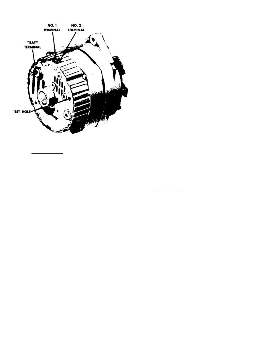
Typical 10-SI Series Generator
c.
Loosen alternator mounting and
adjusting bolts and swing alternator
5-63.
INTRODUCTION:
toward engine far enough to disengage
the V-belt from the alternator pulley.
The DELCOTRON Generator illustrated on
this page features a solid state voltage
d.
Remove mounting hardware and
regulator that is mounted inside the
remove alternator from its mounting
generator slip ring end frame.
All
bracket.
regulator components are enclosed within
a solid mold, and this unit along with
5-65.
DISASSEMBLY:
the brush holder assembly is attached
to the slip ring end frame.
The reg-
a.
Refer to figure 5-79 for parts
ulator voltage setting never needs
identification.
adjusting, and no provision for adjust-
ment is provided.
Scribe a line to matchmark parts
b.
for reassembly in the same relative
The generator rotor bearings contain a
position.
supply of lubricant and require no fur-
ther lubrication.
Two brushes carry
c.
Remove the
four thru-bolts and
current through the two slip ring to
separate the drive
end frame and rotor
the field coil mounted on the rotor and
assembly from the
stator assembly by
under normal conditions will provide
prying apart with
a screwdriver at the
long periods of attention-free service.
stator slot.
The stator windings are reassembled on
d.
Place a piece of tape over the
the inside of a laminated core that
slip ring
forms part of the frame.
A rectifier
bridge connected to the stator wind-
ings contains six diodes and electrically
5-50B
|
|
Privacy Statement - Press Release - Copyright Information. - Contact Us |
